Hm, i've found a working lm3886 macro. Have installed, and got all-over oscillation like Dejan.
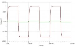
Now, got curious, had removed the control opamp (lm318, opa827), and had left only the bridge driven directly by the generator. Inthe case of the lm4780 macro, i got ~60kHz power response (on 8ohm, 10Vp-p)
With the lm3886 macro installed, the power response of the only bridge is ~210kHz..
I think I need to ask my hp3577, who is closer to reality.
But, as mentioned before, the real full circuit IS stable, and that brings it closer to the lm4780 macro..
Ciao, george
Last edited:
Hi George,
I tried to replace LM3886 in my simulation with LM4780 and now I get a stable circuit, without oscillation.
I used LM3886 TINA-TI Spice Model instead of LM3886 PSpice Model that gave me same problems that you have described.
Based on your measurements, it seems there is some problem with LM3886 model and LM4780 model gives simulation results closer to real world measurements.
I will try to simulate with AD797 and ADA4898-1 models to see what happens. I hope you will get a stable circuit, and hopefully, a great sound.
Best regards,
Dejan
Attachments
In the last weeks my activity on this forum has been near zero,sorry.
September 24th my father died for an incurable pulmonary disease
In the next days I'll try to answer everyone.
September 24th my father died for an incurable pulmonary disease
In the next days I'll try to answer everyone.
I'm very sorry to hear your news, Dario. It must be a very sad time for you. Please take care of yourself and your family first, hifi can wait.
Dario, I'll echo what has already been said and wish you strength in this difficult time for you and your family.
BK
BK
I'm very sorry to hear. I hope those he left behind find peace.
Sent from my iPad using Tapatalk
Sent from my iPad using Tapatalk
So sorry to hear about your father. Know that our prayers are with you and your family. It's a big adjustment, but you will have what's needed to accept and move forward.
First of all, thanks to everyone.
Those caps are not directional, they willl work in both direction but there is, in my experience, a difference in perceveid performance according direction.
The small notch should be on the left, as the small circle on the PCB.
It depends on flux, some is conductive or hygroscopic and so could lead to problems.
In my Lehmann clone build the circuit was oscillating until I've finally cleaned boards.
A (small) perceived low freqs tilt is normal, particularly with Mundorf AGs.
When I read the text on wilma, the micro marking on the side is different.
Is it correct that micro notch should always be on the left.
Shall circle in the marking on the PCB point to me and micro notch on Wilma to the left regardles of text side on Wilma.OR is it the text and the circle side should line up.
PS: anyone who can tell me right mounting Wilma cap.Text on PCBs
not the same way, onely a smal cirkel.Is Wilma directional?
Those caps are not directional, they willl work in both direction but there is, in my experience, a difference in perceveid performance according direction.
The small notch should be on the left, as the small circle on the PCB.
Seems in my haste to install I didn't remove any of the flux from the soldier joints! Quick scribe around with a needle and then a scrub with solvent and brush it was all removed.
Assembled and checked again, no more noise!
I have difficulties to beleive that the resin residuals can cause this kind of problem..
It depends on flux, some is conductive or hygroscopic and so could lead to problems.
In my Lehmann clone build the circuit was oscillating until I've finally cleaned boards.
Now FULLY in line with current BOM and upgraded with all the "audiophile" parts for grins.
Sounding really good with nice authority. Still seems tilted to the low frequencies, but I will run for a few weeks and see where I end up.
A (small) perceived low freqs tilt is normal, particularly with Mundorf AGs.
group buy for FE BOM
Has anyone organized a group buy for the newest FE BOM? With the optimizations, the total cost for the current Ultimate BOM has gotten pretty high. I wonder how much we could save with a group buy? Just curious as the last group buy I was involved in was for the MyRef RevC that Uriah organized.
Has anyone organized a group buy for the newest FE BOM? With the optimizations, the total cost for the current Ultimate BOM has gotten pretty high. I wonder how much we could save with a group buy? Just curious as the last group buy I was involved in was for the MyRef RevC that Uriah organized.
Hi Guys,
did post this initially in the wrong thread, sorry for the double post.
I am afraid my pcbs did lay quite a long time in the corner and I did not buy the parts... 🙁

Is there a chance to get the list of the parts I need, which were in the quoted shopping cart below (which seems not to work any more)?
It is BOM 1.5 with the smd parts already soldered..
Alternatively, if I could use the newer Bom with my older PCB, I would be happy to just use the newer BOM. Is that possible? Has the circuit been updated and do the parts from the new BOM fit with the already soldered SMD parts?
Thanks for your help guys,
Cheers!
did post this initially in the wrong thread, sorry for the double post.
I am afraid my pcbs did lay quite a long time in the corner and I did not buy the parts... 🙁
Is there a chance to get the list of the parts I need, which were in the quoted shopping cart below (which seems not to work any more)?
It is BOM 1.5 with the smd parts already soldered..
Alternatively, if I could use the newer Bom with my older PCB, I would be happy to just use the newer BOM. Is that possible? Has the circuit been updated and do the parts from the new BOM fit with the already soldered SMD parts?
Thanks for your help guys,
Cheers!
Yesterday morning (Saturday) all remaining boards have been shipped.
Hopefully all partecipants will have their kits home in time for Christmas holidays. 🙂
BOM was safe to order from when I've released it, some minor changes (improvements) have been done, though.
- Vishay MBB0207 were not an improvement over KOA MF (but still good enough), so KOA went back in BOM
- Vishay BC 256 PMG-SI from the 'On a budget' BOM resulted so good they're now in the industrial BOM too.
- The NCC LXZ were a bit more neutral than the already very good Panasonic FR so they're now the standard cap for C1,C2.
Nothing that should bother who already ordered it, simply if you're going to order be sure to use latest one using links in the opening post.
Some further small refinement is possible (PTF56 from the On a budget BOM in place of Caddocks MP915 in the Industrial BOM too, for example) but rest assured that any version of the BOM is already safe to order and good sounding.
For partecipants that ordered boards with SMDs already soldered I've added a special BOM that omits the parts already supplied with PCBs:
http://www.mouser.com/ProjectManager/ProjectDetail.aspx?AccessID=fbff7e1d92
Just a note:
- Remember that BOMs are for 1 channel/PCB, order two of them per kit.
- No BOM includes screws and bolts for heatsinks.
Dario
I am sorry for your loss.
Thank you for answering my about the Wilmas.
Take care of Yourself and Your family.
I am sorry for your loss.
Thank you for answering my about the Wilmas.
Take care of Yourself and Your family.
I wonder how much we could save with a group buy?
I never organized a full group buy for two reasons:
- too much work
- increase in shipping costs 'eats' savings on parts
If we order parts for 40 boards BOM's cost drops to 52€, so 17€ less, 34€ per kit.
But shipping cost would double for the added weight and still we didn't considered some form of compensation for the not small work of packaging and labelling of parts.
IMHO the 5-10€ final saving is not worth the effort, things could change with (much) higher numbers like 100 kits (as were for Uriahs GBs, if I remember correctly).
Dario
I am sorry for your loss.
Thank you for answering my about the Wilmas.
Take care of Yourself and Your family.
Thanks and you're welcome.
Last edited:
Is there a chance to get the list of the parts I need, which were in the quoted shopping cart below (which seems not to work any more)?
Just answered on the GB's thread:
http://www.diyaudio.com/forums/grou...men-edition-gb-seventh-run-2.html#post4849004
In general there are two main BOMs up to version 1.20 and from version 1.5.
Four channels of MyRef
Dario, I'm working on getting away from the passive crossovers in my speakers and moving towards active crossovers, using a miniDSP 2x4 initially and eventually a miniDSP 2x4 HD. To that end, I recently signed up for two sets of your next release of MyRef boards.
I will be driving two-way speakers of reasonable efficiency (89db/watt) to moderate sound levels < ~95db. When contemplating the power supply for four channels of amplification, I was initially thinking of using two 200VA 24V toroids and two 100VA toroids, for woofer and tweeter duties respectively.
Thinking about things some more, I'm contemplating using two 400VA 24V toroids with each transformer powering a pair of MyRef amplifier blocks--one pair of MyRefs per L and R channel. Each transformer, with dual secondaries, will power two MyRefs, each driving a woofer or tweeter, per channel. All four amplifier blocks will be in one chassis.
Does this approach sound reasonable?
Last edited:
Dario, I'm working on getting away from the passive crossovers in my speakers and moving towards active crossovers
hello Marc, i am trying to do the same thing with my speakers.
But what electronic crossover you will use?
About the transformers, i think 400 va for 1 channel(2 amps) is a little bit overkill, 300va will be , i think , just fine.
hello Marc, i am trying to do the same thing with my speakers.
But what electronic crossover you will use?
About the transformers, i think 400 va for 1 channel(2 amps) is a little bit overkill, 300va will be , i think , just fine.
I'm going to use the miniDSP 2x4 initially. If I like it I'll go to the miniDSP HD.
Sent from my iPhone using Tapatalk
- Home
- Amplifiers
- Chip Amps
- My_Ref Fremen Edition - Build thread and tutorial