Another option that has been mentioned is the higher grade Sonicaps, but I don't remember hearing from anyone who has tried them. Madisonears may have some information here.
Good news
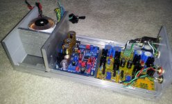
Suburra today tried to ground the heatsink and it seems that the faint hum disappear.
But he tried at home, we will se in the next days if he'll manage to try again with 97dB speakers.
I do agree that, if heatsink grounding doesn't rule it out, is a problem the vast majority of builders will not perceive.
Suburra today tried to ground the heatsink and it seems that the faint hum disappear.
But he tried at home, we will se in the next days if he'll manage to try again with 97dB speakers.
i did notice in the past that if i were to put my finger on the heatsinks on my myrefc, the hum would lessen.
the heatsinks seem to be made out of aluminium, btw.
the heatsinks seem to be made out of aluminium, btw.
Last edited:
Use the PWR_GND tab at the star GND. Heatsink should always have a potential close (or identical) to the audio GND, for electrostatic shielding. At least with a coupling cap (100nF), but direct connection is OK when it does not have contact to anything conducting nearby.
When left floating it's a perfect antenna.
When left floating it's a perfect antenna.
KTSR, That's very interesting as I blew two very good tweeters trying to use this configuration. I thought it had to do with some leakage between the chips and the heatsink but never could track it down. Your description of electrostatics sounds like what I heard - a charge/potential triggering some osculation on the MyRef boards. Probably a constant risk when building on wood without paying close attention to the total ground scheme.

Is that ground direct to earth/safety - or to something back through the board?
I don't know, I wrote him to ask it but I'm pretty sure he connected the heatsink to safety earth.
Probably tomorrow I'll have the answer.
By instinct I would say KSTR's suggestion is a good one.
Last edited:
Suburra answered... he connected the heatsink to PGND on modules, exactly as recommended by KSTR. 😉
At that pad between the two big 10,000 uF caps? If so - good thing you didn't eliminate it as was considered.
At that pad between the two big 10,000 uF caps? If so - good thing you didn't eliminate it as was considered.
Yes, maybe I could add another connector too.
Just out of curiosity - before the FE those caps were C3 & C8. Now they are C101 & C201. I ,apparently mistakenly, was under the impression there was some sort of universal naming convention based on function. Not so, totally up to the designer?
Just out of curiosity - before the FE those caps were C3 & C8. Now they are C101 & C201. I ,apparently mistakenly, was under the impression there was some sort of universal naming convention based on function. Not so?
No, I don't thinnk so.
These names were the same used in the original My_Ref by Mauro.
With the FE I've mantained same names but on the newly designed part (the PS) I've adopted a different numbering.
I did some modification to the PCB layout:
- enlarged by 0.5cm the PCB (same cost for partecipants) so to reposition R10 and R11 like in beta boards.
- revised the DC protection (thanks to the added space) so to have less interaction between various ground returns.
- the C14 cut-out is more similar to beta boards
- added a commodity wirepad to ground the heatsink.
Any opinion, as always, is welcome.
Attachments

Last edited:
Heatsink Ground
Dario,
With all this interesting discussion about grounding the heatsink, will it start to matter if we are talking LM3886T or TF? If memory serves, the T has better heat transfer because the "tab" isn't insulated electrically.
Dario,
With all this interesting discussion about grounding the heatsink, will it start to matter if we are talking LM3886T or TF? If memory serves, the T has better heat transfer because the "tab" isn't insulated electrically.
With all this interesting discussion about grounding the heatsink, will it start to matter if we are talking LM3886T or TF? If memory serves, the T has better heat transfer because the "tab" isn't insulated electrically.
We're talking about TF as specified in all my BOMs. 🙂
Despite the fact the T version has better heat transfer the TF it's specified in BOM for two reason:
- A lot of My_Ref C builder blew their LM3886T for poor insulation (TF it's easier to use)
- The My_Ref (and FE too) don't make so much heat that the T version is needed.
Dario,
With all this interesting discussion about grounding the heatsink, will it start to matter if we are talking LM3886T or TF? If memory serves, the T has better heat transfer because the "tab" isn't insulated electrically.
I too am curious about this. I have not had the opportunity to look into this topic, but as far as I know both versions of the IC should be electronically insulated from the heatsink. Why would you need to connect a ground to the heatsink specifically? Is this because everyone seems to be testing on a wood panel and the heatsink is the only source of chassis grounding at this point? If that is so are you guys also connecting your safety earth connection to the heatsink for testing? I would think that would be necessary. I think most builders will be using metal enclosures and will have the heatsink exposed to the outside air or at a minimum connected to the rest of the metal chassis, either way there has to be a path to safety earth.
as far as I know both versions of the IC should be electronically insulated from the heatsink.
Correct.
Why would you need to connect a ground to the heatsink specifically?
KSTR said perfectly:
When left floating it's a perfect antenna.
Is this because everyone seems to be testing on a wood panel and the heatsink is the only source of chassis grounding at this point?
No, see above.
BTW in a usual build with metallic enclosure, it (and the heatsink in most cases) should be connected to safety earth.
Thanks Dario, somehow I missed that discussion yesterday.
You're welcome 🙂
That depends.BTW in a usual build with metallic enclosure, it (and the heatsink in most cases) should be connected to safety earth.
IF your xformer is rated Class-II (double isolation) and IF you make all the wiring on the primary side also comforming to Class-II and IF the build is sturdy (no on-the-bench loose kind of wiring and components just lying around), THEN (and only then) you do not need to safety-ground the chassis/heatsink and then you can/should connect it to an audio-GND. Just the way most CD-players, smaller integrated amps etc are built.
Note that most off-the-shelf toroids are only rated Class-I, though.
Best of course, especially during the building and early testing process, is to use an isolation transformer, or isolated variac.
- Status
- Not open for further replies.
- Home
- Amplifiers
- Chip Amps
- My_Ref Fremen Edition - Beta build/Fine tuning