In M Jones book Valve amps 3rd edit; section classic amps; page 422: comment; the reduction of Prim Z reduces F3 harmonic with an increase of F2. Highly relevant stuff !
richy
richy
No I didn't see that. Do you have a page number? If not I'll look harder.
Not offhand, I'm at work, where books about valves are a bit out of place. 😀 DF96 has, however, summarized it well.
This amp I've been working on is a push-pull negative feed back and is working well. Trying to impove it some I reduced the voltage on the EF86/6267 stage to supply of 172V. (it has a 100k anode resistor and a 2.2k cathode). In just reducing the voltage I picked up an audible noise and it is electrically everywhere in the system (both channels) looking at it in an oscilliscope. I can also actually hear it and I have resistors for the speakers. Something has gone sonic.
This was not present when the supply voltage was 184V.
Anybody have an idea what this is?
This was not present when the supply voltage was 184V.
Anybody have an idea what this is?
Going back to post #110, My guess is there aren't any screen anode zobels on the output tranny. If you are in serious audio work, and using long cables to speakers, instabilty is guaranteed. Some pics incl. Note; the same ringing effect can occur on the 1st stage without a zobel. This will be a more widespread oscillation.
To specifically point ones finger in the direction where instabilty could be;..we need a circuit diagram.
Changing the 1st stage voltages will upset the loop gain, not by much but, this can upset the screen grid which is usually at a much lower voltage......what is the value of this feed resistor ? (quite high Mohms). Don't put a probe on this point as the probe resistance will probably swamp it.
Using Ipods/pads and other digital playback media are usually designed with the designer without having much clue and no consideration to all the digital noise and hash in the signal. An input 1:1 tranny can do wonders in cleaning this up.
richy
Attachments
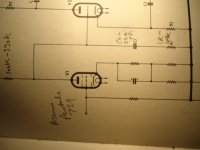
I don't understand some of your nomenclature but it sounds like I need something to block high frequency oscillation. I have attached a couple of pics, one is the 1st stage of the amp (I took it with my iPhone), the other is a pic of the oscilliscope with a 25kc "carrier freq" of the ~250kc oscillation. this 250kc oscillation itself oscillates on and off and I cought it in the pic.
Attachments
BTW I did replace the EF86 on the left channel and the oscillitations sems to have gone away but I must be close the the problem in any case and need to solve it.
You might increasse the gridstop resistor on the first tube from 10K to 47K or even 68K, and be sure it is right at the socket.
Second stage could use gridstops as well, but since they are triodes the value should be fine at 10K.
Second stage could use gridstops as well, but since they are triodes the value should be fine at 10K.
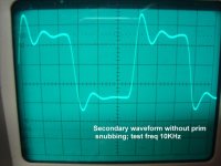
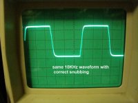
That waveform in 001 pic is not the one I like to see.......suggest you study some of the 1st stage Zobels used ii other designs. All the commerical amps, Mullards, Williamsons use the same procedure of reducing the HF phase angle in the 1st stage anode. pic a bit dull but readable. This should be a good start to eliminating the AM oscillation in pic 001.....Note such oscillations ending up in the o/p stage will show unstable cathode currents...but looking at the secondary may not show it vastly reduced due to o/p tranny bandwidth attenuation.
Sorry for the terminology and the bit "blase" about it all (been doing this for 40 yrs), but there's noway out of the addiction....once you get your "head" into valve amps true and proper, and with the subject of audio engineering to top it, there's a heck of a lot more to come. If you haven't got Morgan Jones books, Valve amps 2-3 ed then get them. It will open you up. I'm not a sales ployer biased to any author but seriously these are a reference, even for nightime thoughts.
richy
Attachments
Going back to post #110, My guess is there aren't any screen anode zobels on the output tranny. If you are in serious audio work, and using long cables to speakers, instabilty is guaranteed. Some pics incl. Note; the same ringing effect can occur on the 1st stage without a zobel. This will be a more widespread oscillation.
To specifically point ones finger in the direction where instabilty could be;..we need a circuit diagram.
richy
Your pics are exactly my problem. Can you clip a section of a schematic so I can study it? If not go into more detail or point me to a reference. I've been learning a lot but have a long way to go. I've looked into my morgan jones book but couldn't find a reference as you mentioned above.
Thanks for taking the time to help.
Morgan Jones Valve amps 3rd ed page 411-2. The book skirts the subject somewhat; Sadly, it doesn't even have the basic example shown in a circuit diagram. The Radiotron handbook 4th ed has virtually nothing.
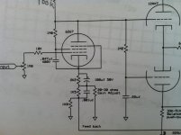
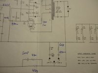
In the attached pic with output stage Zobels is circled red each half.... A silvered mica or hv.polypropylene cap and a small power resistor capable of a few watts depending on the output transformer quality. Note:- Don't pick a bog standard resistor and a capacitor; these components have to dampen the waveform overshoot caused by the parasitics in the output transformer and there is considerable energy and voltage swing.
The finesse is to use the min value components that give an acceptable waveform Q (flatness quality) and avoiding high losses at high frequencies. Be sure to do testing always with a dummy load connected to the output.
The identical approach follows my big power amps over 200W using parallelled tube pairs, the energy is much higher and the components scaled accordingly.
The topic of waveform transient suppression with a view to stability is a complex and very important for an amplifier to be designed to be stable with whatever output load. In a basic 3-4 stage amp with global nfb, there are 3 variables in the feedback paths that interact with each other. The 1st stage Zobel; the output stage UL zobel (anodes to screens); and the step response in the global negative feedback all conflict.
If a design takes one out then things become easier.
Those of us who have/had careers in commercial switchmode magnetics design, then the related leakage inductance and capacitance is much more important with a view of reducing radiated EMI issues in the transformer, and efficiency snubbing with zobels becomes much easier to grasp.
richy
Attachments

John Moyle has a good article on feedback that touches on the subject but refers to the network as a "Step Circuit" when he uses it in the first stage anode. (Part 2 page 2)
http://www.tubebooks.org/file_downloads/moyle_amp.pdf
http://www.tubebooks.org/file_downloads/moyle_amp.pdf
John Moyle has a good article on feedback that touches on the subject but refers to the network as a "Step Circuit" when he uses it in the first stage anode. (Part 2 page 2)
http://www.tubebooks.org/file_downloads/moyle_amp.pdf
I read this. It's a good article and explains a lot. Thanks.
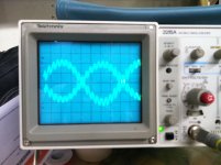
Thanks, I believe I understand the schematic. It seems to short/quench the ring from the transformer. My amp does not have 40% transformer taps (see schematic pdf) but it seems I can do the same thing by putting a cap and resistor between each HV tap and the center tap. My ring (see jpg pic) seems to be about 20kc. The square wave is 1kc. Please comment on this approach.
Attachments
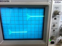
Looks like ringing is probably a little higher - circa 25kHz.
You may benefit from using a MOV-R series 'zobel', compared to a C-R, for positioning across the OT primary half-windings. The MOV-R network can provide over-voltage protection across those winding sections, but requires sourcing a MOV (or series MOVs) with suitable DC voltage ratings and suitable inherent capacitance values - typ 100pf to 1nF range (depending on disk size) with DCV from 240 to 600V (1mA level, for common AC mains voltage level applications).
You may benefit from using a MOV-R series 'zobel', compared to a C-R, for positioning across the OT primary half-windings. The MOV-R network can provide over-voltage protection across those winding sections, but requires sourcing a MOV (or series MOVs) with suitable DC voltage ratings and suitable inherent capacitance values - typ 100pf to 1nF range (depending on disk size) with DCV from 240 to 600V (1mA level, for common AC mains voltage level applications).
The Zobel circuit used across the UL 43% taps to anodes- should not be used across each true pentode operated half primary i.e anodes to B+ ; (which used to be a classic class B approach). The voltage swings are high leading to considerable losses in the Zobel components. A better place is across the whole secondary winding and again none of this is discussed in any papers, the classic circuit is the Radford STA100 of 1967. (in pic).
Personally I don't like the sound of this amplifier, raucous and too highly strung with 600V on KT88's ended up with a short life, and it was from experience with this amp on stage, by not having a screwdriver on hand to change the shunt Zobel feedback connections on the secondary for a specific speaker, that I changed my tact to working on amplifiers with modest amounts of feedback. As everyone in MI knows, mismatched speakers get connected to amplifiers whatever the make and impedance, and are expected to work not squeal in protest !
Moyles article of 1958 coupled with previous ground work done by Williamson and Langford Smith (Radiotron Handbook) were advanced in their day in understanding the issues. IMO, the components that "give the game away" in Moyles 17W design is the 470pF and 4K7 in the EF86 anode circuit. These relatively high Zobel values for a pentode stage illustrates the amount of HFcurtailment required for phase correction, is testament of the higher leakage parasitics of output transformers of that vintage. What the article fails to mention is how these components effect the audio distortion in the whole amplifier at critical audio frequencies traded against loop gain. It's not all cream....the square wave may be excellent but the THD could be quite high too by not optimising these components..
Perhaps I should spend more time putting my own findings together in a comprehendable text.
richy
Attachments
Last edited:
There are plausible advantages to applying the zobel across each half-primary for non-UL PP. This winding section has the most turns, and a damped RC directly across the winding may well achieve better control of first self-resonance than a coupled load zobel. If the transformer self-resonances are highish, then the zobel values are unlikely to cause excessive losses - certainly for guitar or PA use where signal is attenuated within the source-amp chain for above audio band levels.
The Zobel circuit used across the UL 43% taps to anodes- should not be used across each true pentode operated half primary i.e anodes to B+ ; (which used to be a classic class B approach). The voltage swings are high leading to considerable losses in the Zobel components. A better place is across the whole secondary winding and again none of this is discussed in any papers, the classic circuit is the Radford STA100 of 1967. (in pic).
Personally I don't like the sound of this amplifier, raucous and too highly strung with 600V on KT88's ended up with a short life, and it was from experience with this amp on stage, by not having a screwdriver on hand to change the shunt Zobel feedback connections on the secondary for a specific speaker, that I changed my tact to working on amplifiers with modest amounts of feedback. As everyone in MI knows, mismatched speakers get connected to amplifiers whatever the make and impedance, and are expected to work not squeal in protest !
richy
Thanks for the comments. Should you write a compresensive anything about this please post a link here. Thanks
There are plausible advantages to applying the zobel across each half-primary for non-UL PP. This winding section has the most turns, and a damped RC directly across the winding may well achieve better control of first self-resonance than a coupled load zobel.
There is a conflict..with Zobels fitted across each half primary, I've found in every case with staightforward non UL AB amps, thd rises more with rising frequency than the output transformer alone does, as the output tubes fight the extra Zobel and transformer parasitics impedances...the phase angle rubik plays tricks, but the squarewave ring and damp does reduce within the output stage but isn't the end story. One must also look elsewhere and o/p transformers with such poor stats, the only way is to reduce circuit bandwidth.
This is one of many reasons that the o/p tranny quality in valve amps is such a depending item.
richy
Yes the trick would be to introduce just enough zobel impedance to alleviate the impact of the Q of the first resonanance, but not introduce significant early phase shift - which would probably place the zobel corner significantly above the first resonance, with the zobel resistor having something like a PP impedance value. Placing the zobel corner near the first resonance would probably be way too heavy handed.
A zobel resistance similar to PP impedance value is also aimed at dampening any over-voltage transient where the MOV starts conducting, if using a MOV-R zobel.
A zobel resistance similar to PP impedance value is also aimed at dampening any over-voltage transient where the MOV starts conducting, if using a MOV-R zobel.
- Status
- Not open for further replies.
- Home
- Amplifiers
- Tubes / Valves
- My Wave Isn't Square.