

Some SE transformers are not so bad.
40Hz!
1000Hz
40Hz!
An externally hosted image should be here but it was not working when we last tested it.
1000Hz
An externally hosted image should be here but it was not working when we last tested it.
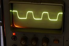
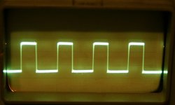
To say the same in other words, the second waveform shows some loss of bass frequencies.
To be more precise: rounded leading edge: lack of treble; sloping tops: lack of bass (relative to the frequency being displayed).
And the assimetry is the norm, not the exception, in SE designs. 🙁
Not only the tube is assymetrical, but the iron too, because it´s strongly DC biased towards "one side" of its hysteresis curve.
As a side note: if you want perfect squarewaves, go SS .
No kidding.
Well, this is another SE design on my test bench...
An externally hosted image should be here but it was not working when we last tested it.
Wich transformers you used?
Well, this is another SE design on my test bench...
An externally hosted image should be here but it was not working when we last tested it.
AE 40 watt Silver 😀Which transformers you used?
Nice result you got for 40Hz but it's taken at low power isn't it?
Last edited:
You can see in the picture how large the signal is. It's at low power but SE is almost always low power, isn't it? This transformer was designed for 3500 ohm 13W 18Hz.
AE 40 watt Silver 😀
Nice result you got for 40Hz but it's taken at low power isn't it?
1,65Vrms was just before core saturation? That square wave starts to behave like DC at low frequencies, not?
No, it was just a signal, random.
1,65Vrms was just before core saturation? That square wave starts to behave like DC at low frequencies, not?
That's the RMS value of the output voltage Andrew. The scope knobs shown are of the first channel, measurement is done with channel two.
This will probably hold for all amps but I measured that with the rise of output power F-3dB is moving slowly up in frequency. Possibly because of the SE topology I measured with the rise of output power more frequency dependant deviation. iaw, the lower the output power, the more constant the amplification becomes. All according the text books 😉
Tested with sine wave the big amp reproduces comfortably down to 30Hz. From a certain power level losses in the low frequencies are becoming substantial. 20Hz was at -30% at 9W. Not bad? The sinus did not look much distorted but it remains hard to see. Looking for output voltage alone won't cut it...
An externally hosted image should be here but it was not working when we last tested it.
Last edited:
I think it's better to do square waves at a lower output. It doesn't makes sense to do this at high/max power.
I use square wave to see if the transformer has overshoot/resonance (i use 10kHz and 20kHz mostly).
Also a normal frequency measurement,1Hz to 1 Mhz, at low power (~1W) and sometimes at very low power to see what the influence is of the permeability.
I use square wave to see if the transformer has overshoot/resonance (i use 10kHz and 20kHz mostly).
Also a normal frequency measurement,1Hz to 1 Mhz, at low power (~1W) and sometimes at very low power to see what the influence is of the permeability.
OK, that's the answer I was fishing for in post #165 😀
You're testing the transformer, I was testing the amplifier.
The high power sinus wave was to determine the amps power bandwith.
You're testing the transformer, I was testing the amplifier.
The high power sinus wave was to determine the amps power bandwith.
Last edited:
Testing the amplifier at low and very low power could be more interesting then only high power.
Give it a try 🙂
Give it a try 🙂
OK, that's the answer I was fishing for in post #165 😀
You're testing the transformer, I was testing the amplifier.
The high power sinus wave was to determine the amps power bandwith.
I did. It's just that for low power listening I would not take a SE penthode but a SE triode amp.. and these have their best watt first 😉 When overall feedback is applied a compensation network might clean up oscillation and minimise ringing on the leading edge, not withstanding the demand for keeping sufficient bandwidth.
If you're applying a 20KHz sw your transformer has to pass 200KHz worth of harmonics. Almost every opt will end up with a rolled off and distorted leading edge. What's interesting in that?
If you're applying a 20KHz sw your transformer has to pass 200KHz worth of harmonics. Almost every opt will end up with a rolled off and distorted leading edge. What's interesting in that?
You can do without a 10kHz (or 20k) square wave but it's a easy way to see if your amplifier (transformer) has problems.
Good amplifiers/transformer have nice square waves even at this frequencies (maybe a little bit rounded but no ringing)
This would be reasonable:
20kHz
Or 10KHz
Brand X ( Audionote 2k6/8 Ω) at 10kHz
Also AN (very nice response i think)
Good amplifiers/transformer have nice square waves even at this frequencies (maybe a little bit rounded but no ringing)
This would be reasonable:
20kHz
An externally hosted image should be here but it was not working when we last tested it.
Or 10KHz
An externally hosted image should be here but it was not working when we last tested it.
Brand X ( Audionote 2k6/8 Ω) at 10kHz
An externally hosted image should be here but it was not working when we last tested it.
Also AN (very nice response i think)
An externally hosted image should be here but it was not working when we last tested it.
I did. It's just that for low power listening I would not take a SE penthode but a SE triode amp.. and these have their best watt first 😉 When overall feedback is applied a compensation network might clean up oscillation and minimise ringing on the leading edge, not withstanding the demand for keeping sufficient bandwidth.
If you're applying a 20KHz sw your transformer has to pass 200KHz worth of harmonics. Almost every opt will end up with a rolled off and distorted leading edge. What's interesting in that?
Last edited:
Isn't it so every transformer is ringing? By manipulating (dampening) the circuit one can minimise this phenomenon.
Probebly no resonances but it is asymetric.
here is my SET 20Khz square wave ( don't remember output level but not higher then 1 or 2 W)
Well, try to compensate this:
1 brand X transformer with frequency problems, second brand Y with less problems but slighty lower frquency response.
This is the square wave brand X
This brand Y
An externally hosted image should be here but it was not working when we last tested it.
1 brand X transformer with frequency problems, second brand Y with less problems but slighty lower frquency response.
This is the square wave brand X
An externally hosted image should be here but it was not working when we last tested it.
This brand Y
An externally hosted image should be here but it was not working when we last tested it.
Isn't it so every transformer is ringing? By manipulating (dampening) the circuit one can minimise this phenomenon.
Last edited:
Probebly no resonances but it is asymetric.
there is problem with my old square wave generator...F5 Amp @ 20khz looks the same...
Attachments
- Status
- Not open for further replies.
- Home
- Amplifiers
- Tubes / Valves
- My Wave Isn't Square.