In varying the cathode resistor and anode resistors of the 12AX7 looking for balanced inversion, I discovered quite by accident that there must be an infinite list of pairs. I ran into 2 pairs that gave balanced output on the long tail pair and assumed that there must be a linear relationship. I used these 2 pairs and plotted a straight line. The pic is attached. I had always just assumed there would only be one combination to use as this is what I have always seen on schematics (100k and 68k). The values I ran into are 100k and 82k and 39k and 55k for the supply voltages I have for the EF86 (146v) and 12AX7 (273v). The second pair was odd as the anode resistor was smaller that the cathode. Both gave the same voltage gain.
Is this common knowledge? Comments would be appreciated.
On to my current problem. Using resistors as output loads the outputs looked good on an oscilloscope, but with some small remaining hum. When I hooked the amp up to speakers to play music I heard an on/off noise which I guess one could call motorboating. Morgan Jones mentions this and his solution is to use a “HT regulator” but does not mention how to get this done. Anyone know how to do this?
Attachments

LTP...is this common knowledge ?
Yes it is. The basic LTP is sensitive to variations and citations of yesteryear often quoted dysymmetry between anode AC voltages from each half often quoting a 5% difference.. can be ignored. One can get much improved performance by using a CCS in the common cathode tail.
Putting it briefly; The nub when using global nfb that many misunderstand. Remember the amp with global nfb including the o/p tranny that now includes every part of the circuit within the feedback path behaves like a controlled and stable AC phase locked loop and the global nfb will attempt to make up for circuit deficiencies on a cycle per cycle basis on the condition there is enough loop gain available and that the gain/phase angle relationship as plotted on a Bode plot never goes towards instability. This may seem complicated but a successful amp design will follow such pattern.
A simple test is to deliberately place a component more than 20% tolerance i.e, as you have done; a poor section of an LTP; or a well used tube in one half push pull and one will find the nfb loop does it's best to compensate. One also needs the minimum loop gain to do the job.
Hence, twe arrive at the old adage of power tube manufacturing tolerances; one should be able to minimised differences by selecting two out of three tubes in a batch with similiar anode currents to make a reasonable match...This raises the fussy issue of some audio gurus insisting perfectly matched tubes...for each p-p half when the earlier part of the circuit may be wildly out....Can anyone really tell the difference on a swap ?
richy
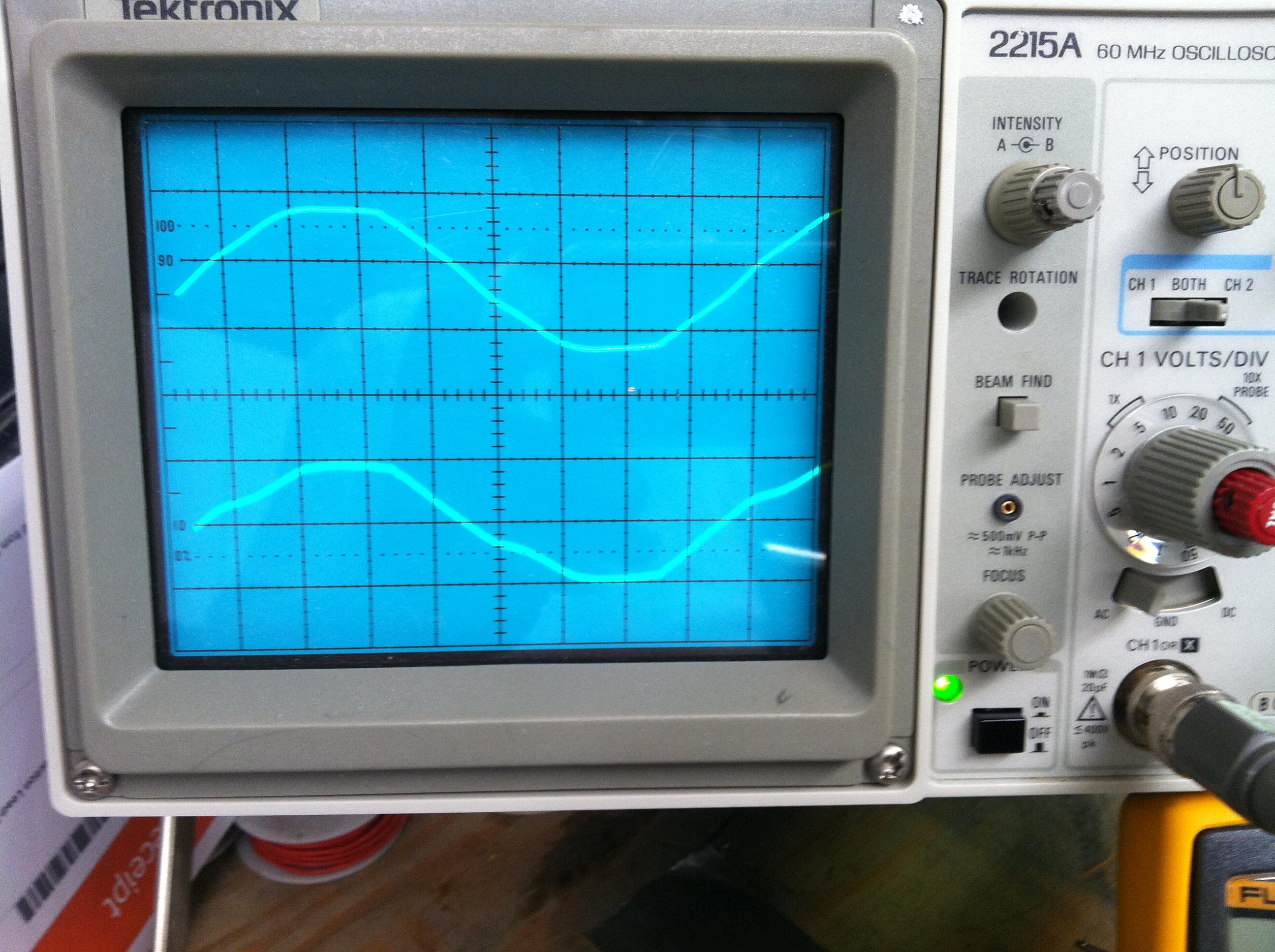
I have noise at 12.5cps that I cannot get rid of nor can I locate the source. I have included a pic of the scope which shows about 14mv of noise on the EF86 anode which I originally thought was 60cycle hum. Having broke my signal generator (shorted it to HT) I spent some time looking for the source of the hum. I can reduce it by 1/2-1/3 it's amplitude by shorting the feedback to ground but that does not get rid of it With the inputs shorted to ground I would think that my output should be flat.
Can anyone give me some hints where I can look?
Can anyone give me some hints where I can look?
Attachments
Sounds somewhat like a power supply capacitor motorboating problem. LF instability agrivated by global feedback. Add an additional filter cap temporarly to each stage one at a time and see if the frequency changes. If so, look at your decouplling. Also try disconnecting your feedback to see if it goes away.
Are we dealing with the same amp with the squarewave overshoot issues ? or is this another amp with 12 Hz warbling ? As Gimp mentions disconnect the global feedback loop and see results. If this is the same amp, We need to return to the circuit diagram.
richy
richy
Thanks guys for the suggestions. Yes, this is the same amp with the ringing on square waves. I have not solved yet as I have broken my signal generator and waiting on a new one. I have, however, found the problem with the low frequency "hum". I misread the scope (it is 5 times 12.5cps) and found it is 60 cycle hum coming from the heater currents. The entire schematic is contained on a PCB and I mistakenly grounded the heater currents in the board ground. A big mistake. I confirmed that the 5 and 6 volt grounds in the PCB show up on every cathode. The pic shows what I found. The top trace is 6.3 volt heater from an EL84 and the lower trace is the cathode on the EF86. It seems everthing I do is a learning experience. I truly do thank you for your help. I know you're shooting in the dark not knowing the details of what I'm trying to do. You have always, however, pointed me in the right direction.
Attachments

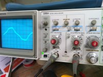
This is the same push-pull negative feed back amp youall have been helping me out on. I think I am finished but would like your comments on the following. The amp has a resonance at 30-35kc and again at ~70kc. This is with it connected to load resistors rather than speakers. I have not been able to remove them. The ring on a 1kc square wave excites these frequencies, hence the ring. I can get rid of most of the 70kc but it's probably not worth it. I have no idea why the resonances are there. The phase of the feedback is lagging the input slightly but not enough to cause these resonances. Comments on possible causes and solutions would be appreciated.
http://www.diyaudio.com/forums/atta...17247292-my-wave-isnt-square-vmx-pics-009.jpg
That to me looks like output stage clipping....are you measuring correctly ?
richy
That to me looks like output stage clipping....are you measuring correctly ?
richy
RE: the pic you referenced
The top trace if from the 6.3 volts for the heaters.
The 2nd trace is from the cathode of the 1st stage (EF86)
So I'm quite sure the hum is from the heater voltage which I allowed to be in the PCB and should not have. What I can't find is the reason for the square ring at about 30-35kc which shows up in a 1kc square wave.
Got an upto date circuit diagram ?
I'm working on one trying to it catch up. Since the last post I did however find that by changing the input POT I could alter the ring a considerable amount and actually get rid of it except for the 70k ring. The 30k I could make go away by turning the pot to a specific spot. The schematic of the front end (which is correct) is attached. Do I have a crappy POT? I got the 1meg audio pot from my distributor.
Attachments
This is the same push-pull negative feed back amp youall have been helping me out on. I think I am finished but would like your comments on the following. The amp has a resonance at 30-35kc and again at ~70kc. This is with it connected to load resistors rather than speakers. I have not been able to remove them. The ring on a 1kc square wave excites these frequencies, hence the ring. I can get rid of most of the 70kc but it's probably not worth it. I have no idea why the resonances are there. The phase of the feedback is lagging the input slightly but not enough to cause these resonances. Comments on possible causes and solutions would be appreciated.
Well I have solved all my problems except this 60cycle hum. The small (50ma) ripple is driving an oscillation that peaks about 1 volt on the speaker output. Adding more caps and reducing the ripple makes no difference. The oscillation still peaks at 1 volt on the speaker output. Is there any way to kill this w/o reducing the low frequency response? Any suggestions would be helpful. The coupling caps to the EL84 are .47uf and I hate to reduce them but will if that is the only way.
Found the hum problem. The heater current from the transformer was not grounded and the EF86 screen had a lot of 60 cycle hum on it which was amplified. So I grounded what looks like the traditional way by grounding the center tape. This reduced the num to 4mv, a big improvement. However; if I ground one end of the heater wires and not use the center tap my screen hum is reduced to .5mv which is much better and can hardly be heard. So is this acceptable or does this create a problem?
What distortion renders this 1KHz sw crooked in the second picture?
Circuit at hand is SE penthode (RH84).
Circuit at hand is SE penthode (RH84).
An externally hosted image should be here but it was not working when we last tested it.
An externally hosted image should be here but it was not working when we last tested it.
The top one reads ~4div and it's set to 0.5V/div, i.e. 2Vpp
But the meter reads 3.2Vrms
The bottom one reads ~7.5div, i.e. 3.75Vpp and the meter reads 6.1Vrms
Is the amp near clipping.
That would "square up" a sloping top.
Sloping hoizontals are an indication of lost fundamental.
But the meter reads 3.2Vrms
The bottom one reads ~7.5div, i.e. 3.75Vpp and the meter reads 6.1Vrms
Is the amp near clipping.
That would "square up" a sloping top.
Sloping hoizontals are an indication of lost fundamental.
The distortion in the second waveform shown is due to low frequency phase shift, essentially there is some high pass filtering going on somewhere in your amplifier - could be output transformer related or coupling cap related. A schematic of the amplifier with values might help.
It's also not symmetric top and bottom, suggesting a transformer shortcoming- I'm not familiar with this design, does it have any local feedback from the output tube plate so that the source impedance to the transformer is reasonable?
Looks like a problem with frequency reponse for low and higher frquencies.
For large signals the output impedance could be a problem. (No current available at 1/2 of the signal, and maybe to less induction at 1/2 of the signal for the SE transformer)
For large signals the output impedance could be a problem. (No current available at 1/2 of the signal, and maybe to less induction at 1/2 of the signal for the SE transformer)
What distortion renders this 1KHz sw crooked in the second picture?
Circuit at hand is SE penthode (RH84).


Last edited:
To say the same in other words, the second waveform shows some loss of bass frequencies.
To be more precise: rounded leading edge: lack of treble; sloping tops: lack of bass (relative to the frequency being displayed).
And the assimetry is the norm, not the exception, in SE designs. 🙁
Not only the tube is assymetrical, but the iron too, because it´s strongly DC biased towards "one side" of its hysteresis curve.
As a side note: if you want perfect squarewaves, go SS .
No kidding.
- Status
- Not open for further replies.
- Home
- Amplifiers
- Tubes / Valves
- My Wave Isn't Square.