Ed, what's your US source. I havent looked yet, but I tend to order large quantities these days. Might get the for the kit, if the price is right.
On the split C2/C3 issue, my schematic didn't split the cap (i.e. I only had one), Kari split the cap for layout convenience on his boards. That being said, the split doesn't create any problems, and on the layout side solves a few. I never did use a pcb for my preamp, building everything on perfboard psuedo point to point.
I really like that Russ has managed to put the gain/cascode fets along one side for easy heatsinking. Even though I don't really need any, I'll definitely be buying a set or two in case I decide to rework my preamp later.
For those who were interested the link to my schematic is here.
Cheers, Terry
I really like that Russ has managed to put the gain/cascode fets along one side for easy heatsinking. Even though I don't really need any, I'll definitely be buying a set or two in case I decide to rework my preamp later.
For those who were interested the link to my schematic is here.
Cheers, Terry
Brian, here is my source in EU. They do overseas also😉 If you would take over, that would maybe be the best solution?? Would save me some work at least😀 Whatever, if you need my help, let me know🙂Ed, what's your US source.
I usually buy the Rifa PHE's from Elfa. Here is the link:
http://www.elfa.se/dk/ Just select Language in the upper section!
Best of luck
Steen.
Is that "Steenoe caps" legend staying on the boards😀 I would love it ofcourse😎 Russ, you did a great job🙂 Thanks a lot for all your efforts🙂
Steen😎
Steen😎
Domestic Evox Rifa
Thanks for the offer, steenoe. Very generous and under consideration.
Brian, Going to the Evox/Rifa site:
http://www.evoxrifa.com/n_america/index.html
enter the key for the package desired in the "search" window.
Try PHE426 for snorts and giggles...
The results will include stock on hand at domestic vendors. Finding everything needed at one vendor and/or meeting minimum purchase requirements for them seems to be at opposite ends of the spectrum.
Russ, whats up next??😀 😀 I am a bit excited😉 A-X, maybe? There is a certain demand for those boards on a continuos basis!!
Steen😎
Steen😎
To me also😉A-X though sounds good to me.
I have a few ideas about that one!
Steen😎
Ps. Russ, you are a blessing to us😉 😉
Russ,
Yes I see, Metalman's schema also shows the same thing, but he used only one cap so he could not possible connect it the way the schematic shows.
What I mean is that both positive terminals of those caps should have a common connection and not through 2 resistors from B+.
The way it is connected each cap will feed ½ of the circuit and will impair the common mode rejection ability of this circuit since the feed voltage will be different at any given time.
The way to solve this is just using one resistor that feeds a common connection to the positive of both caps.
Kristijan conection is correct, have a look to the schema that also uses two caps that Steen pointed.
metalman said:On the split C2/C3 issue, my schematic didn't split the cap (i.e. I only had one), Kari split the cap for layout convenience on his boards. That being said, the split doesn't create any problems, and on the layout side solves a few. I never did use a pcb for my preamp, building everything on perfboard psuedo point to point.
I really like that Russ has managed to put the gain/cascode fets along one side for easy heatsinking. Even though I don't really need any, I'll definitely be buying a set or two in case I decide to rework my preamp later.
For those who were interested the link to my schematic is here.
Cheers, Terry
Terry, your shematic is correct but not the one Russ is showing.
Tony, I am sure you are right about this , being persistant as you are🙂 As usual we have to listen up, when you point something out😉 I will give it all a thorough look! Russ, do not send the board to production before this is solved, please
Steen😎
Steen😎
Yes, I actually completey agree with tony. I was following the schematic from Karis thread which I assumed was faithful to Terry's. I see now it is not. 🙂
It is an easy change.
I need to know how much power should the single resistor from V+ in to the caps dissipate.
Thanks!
Russ
It is an easy change.
I need to know how much power should the single resistor from V+ in to the caps dissipate.
Thanks!
Russ
To determine the size of a 22R we need to know the bias (Amps) of this circuit. I remembered it was quite high and almost sure we will need at least 3 W.
The original BOZ did draw 80mA per channel with similar source resistors and 60V rails.
If we have a similar bias to this circuit we only need a 1/2 W resistor (22R) with a good margin.
Russ, make it a true 1/2W not the smallish ones that now sell as 1/2W.
If we have a similar bias to this circuit we only need a 1/2 W resistor (22R) with a good margin.
Russ, make it a true 1/2W not the smallish ones that now sell as 1/2W.
Russ, hate to call your attention once again but we have some differences against Metalman’s circuit on the CCS section, both, connection and value, the former being more important at this point. Please have a look.
I would also add a small film cap parallel to D1 (Z5 on Metalman’s). And is not a bad choice to also add – if space allows – small film caps to Ref 1/2 (Z6/7) specially if someone is using zeners.
P.D. Should have said BOSOZ on my previous post
I would also add a small film cap parallel to D1 (Z5 on Metalman’s). And is not a bad choice to also add – if space allows – small film caps to Ref 1/2 (Z6/7) specially if someone is using zeners.
P.D. Should have said BOSOZ on my previous post
Gentlemen,
Sorry to have created confusion. Kari indeed used a different CCS than I did, but as Kari's was/is a valid CCS design, I had decided not to comment on it. Guess I should have spoken up.
On the other items under discussion: I didn't use one but I can't argue on the film cap across D1, it is a good idea. I did a fair bit of auditioning on my preamp with and without caps across the cascode voltage references, and at least to my ears I could not hear any difference between the two configurations. In the end I left them in because I didn't feel like spending the effort to take the caps out. Lastly, apassgear is on the ball with regards to the 22R resistors, I used 1/2 watt resistors in those positions myself, and the circuit bias is 80mA per channel.
Lastly, I realized that my schematic is missing the 221R gate resistors for the cascode fets, which I did use and are necessary for stability.
Again I apologize for creating extra work. But I promise that the end result will be worth the efforts
Really nice project guys, well done!
But I have a purely imaginary problem with the pcb. I hate the look of curved traces. Stupid, I know, but I just do. Looks like I'll be making my own after all! 🙂
But I have a purely imaginary problem with the pcb. I hate the look of curved traces. Stupid, I know, but I just do. Looks like I'll be making my own after all! 🙂
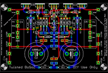
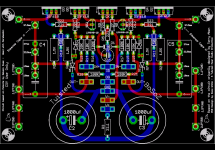
Please excuse my ignorance, but I am left a little puzzled. Here is my latest layout and schematic.
I am not too concerned about the CCS as long as it is good. If I can do it better in the space I have I will.
I think adding a film cap accross D1 is doable, maybe even Ref1 and Ref2. I am thinking 100nf, is that ok?
I should have noted it ealier, but I do know this is not purely metalmans circuit, but a sort of hybrid of Terry's and Kari's circuits.
Anyway here is what I have now. Please give me some more guidance as to what this thing "should" look like. I don't want to screw anything up.
Attachments
- Home
- Amplifiers
- Pass Labs
- My Take on X-BOSOZ