How much space do the output caps have? abd what is the pin distance for them?
How do you want to heatsink the fets?
How do you want to heatsink the fets?
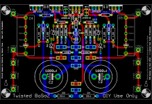
Very nice Russ🙂 If you look at it, there is a "Twisted X" in the middle😉 Cool.New improved safer version. 🙂
All the fets can be mounted on the same heatsink. Like you would do in a poweramp, just in a smaller scale. Thats actually pretty good. All the fets will have the same temp.How do you want to heatsink the fets?
Steen.🙂
Don't be so sure of thatOriginally posted by steenoe All the fets can be mounted on the same heatsink. <SNIP> All the fets will have the same temp.[/B]
 😀
😀/U.
I guess you are right Nisbeth. Nonetheless they stand a better chance tracking the temp when mounted on the same sink, instead of having 5 seperate sinks, dont they?😉Don't be so sure of that
Steen😎

Russ,
I had a closer look to the layout this morning and if you don’t mind I would like to point a couple of small things I would do different:
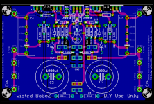
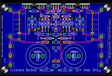
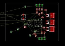
R12/13 should finish as close as possible to the gates of the FET. I think is doable if you have those resistors in an upright position and moving the red traces a bit downwards.
You have fastons on the input signal and both pins seem to connect to the input. In my opinion one should be ground to properly terminate the ground input to the pcb. I myself will not use the faston connector for the input but of course that’s optional.
I guess that more important that a ground plane is to have a correct star grounding for the input.
I might have some other suggestions but that will take me a while to look over the schematic and layout.
🙂 🙂 🙂
I had a closer look to the layout this morning and if you don’t mind I would like to point a couple of small things I would do different:
R12/13 should finish as close as possible to the gates of the FET. I think is doable if you have those resistors in an upright position and moving the red traces a bit downwards.
You have fastons on the input signal and both pins seem to connect to the input. In my opinion one should be ground to properly terminate the ground input to the pcb. I myself will not use the faston connector for the input but of course that’s optional.
I guess that more important that a ground plane is to have a correct star grounding for the input.
I might have some other suggestions but that will take me a while to look over the schematic and layout.
🙂 🙂 🙂
Thanks,
I will see about R12/R13, thanks for the note.
As far as the fastons, they are terminated properly because the single faston connectors have two legs which fit in the pair of mounting holes. So one faston pin = two holes. The hole spaceing is .2" so if you wanted you could probably find terminal blocks that fit. Also the pads for the pairs of faston holes for each faston make excellent wire pads for direct wiring.
So, there are 3 input fastons (IG, In-,In+) and 3 output fastons (OG, Out+, Out-)
Notice I kept the star grounding even when adding the ground plane. The GND plane is purely there as an RF shield. I personally don't think it necessary, but it should not hurt, and I figure some folks will like it. I like to provide clear equal conduits back to the power ground.
Cheers!
Russ
Member
Joined 2002
jleaman said:What color are you going to do the boards ?
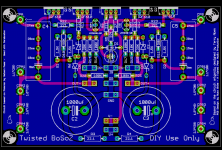
Green. Its sort of a twisted pear tradition. Simple roots.
Though I hardly know why it matters. 😉
Green is good. You do get tired of red or blue boards, for some reason😱 Doesn't happen with the green ones🙂Green. Its sort of a twisted pear tradition. Simple roots.
Steen🙂
Member
Joined 2002
steenoe said:Green is good. You do get tired of red or blue boards, for some reason😱 Doesn't happen with the green ones🙂
Steen🙂
Black with white letters OR gold like Peter d's 😀
Russ White said:
So, there are 3 input fastons (IG, In-,In+) and 3 output fastons (OG, Out+, Out-)
Cheers!
Russ
I got that on a second look to the layout. In any case I would suggest only two double fastons, each one with the signal and ground since it will be easier when using a coaxial cable to carry the signal and for those using it single ended.
Regarding GP I would prefer sans, but let’s see what others have to say about it.
🙂 🙂 🙂
Member
Joined 2002
Re: Moved R12/R13
Russ, what is the dimensions of this board ?
I'm trying to work on my SMD version of the aleph mini's 😀
I think i shal be asking you to look over my boards to see your suggestions and idea's 😀
Russ White said:New layout, symmetry not as good now though. 🙂
Russ, what is the dimensions of this board ?
I'm trying to work on my SMD version of the aleph mini's 😀
I think i shal be asking you to look over my boards to see your suggestions and idea's 😀
Re: Re: Moved R12/R13
4.6" x 3" roughly
jleaman said:Russ, what is the dimensions of this board ?
4.6" x 3" roughly
Member
Joined 2002
- Home
- Amplifiers
- Pass Labs
- My Take on X-BOSOZ