Cheer up mate🙂 You will have so much more satisfaction from a real NP system, that you will forget about all your previous.................. Do I need to say more, just let me know😉Darn..
All the chipamp guys will get surprised😀 😀
Steen 😎
Coming in a bit late I guess...
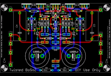
This might be the best layout by far I’ve seen for this preamp. Excellent work Russ, please receive my congratulations, I like those FET’s aligned to the side of the board which makes them easy on heatsinking, 😎 at least from my humble DIY point of view.
One thing I noticed on the schematic is the lack of protection on Q4/5 gates. I know many of us don’t like zeners there but being a passive devise as long as the voltage is not exceeding the zener rating it does not intrude on the signal.
If this is going to be a group buy I would suggest having the opinion from other members interested on the boards. I would vote to add them and if someone doesn’t like these just don’t solder them.
I’m in for a couple of boards
Russ, what is the lead spacing of the C4/C5 caps on the amplifier board? If I'm reading it right it's 15mm and finding a 10uF film cap in that package is hard to say the least. Did you have a specific part in mind when you chose that footprint?
/U.
/U.
That is correct Tony! How was that to be missed?If this is going to be a group buy I would suggest having the opinion from other members interested on the boards. I would vote to add them and if someone doesn’t like these just don’t solder them.
Steen😎
No worries 😀
i,m looking forward to get my hands on these boards. 😉
sub or no sub..--- i want one 😎
/Z
i,m looking forward to get my hands on these boards. 😉
sub or no sub..--- i want one 😎
/Z
Nisbeth said:Russ, what is the lead spacing of the C4/C5 caps on the amplifier board? If I'm reading it right it's 15mm and finding a 10uF film cap in that package is hard to say the least. Did you have a specific part in mind when you chose that footprint?
/U.
Hi Nisbeth,
I have some MKPs that fit, but I am willing to add some more pads for bigger radial type caps.
I actually plan on using 33uf axial foil caps.
EDIT forgot to mention that the LS is for 10 or 15mm caps, which you can get.
Cheers!
Russ
Re: Coming in a bit late I guess...
First of thank you so much. I have been having a lot of fun with this project. Great designs naturally inspire interesting layouts. 🙂
This is my first ever Pass design, and yes even my first ever FET design, so I am not sure how to implement what you are asking for as far as the Q4/5 gate protection zeners. Let me take a stab at it.
A quick description would be very helpful.
Cheers!
Russ
apassgear said:One thing I noticed on the schematic is the lack of protection on Q4/5 gates. I know many of us don’t like zeners there but being a passive devise as long as the voltage is not exceeding the zener rating it does not intrude on the signal.
First of thank you so much. I have been having a lot of fun with this project. Great designs naturally inspire interesting layouts. 🙂
This is my first ever Pass design, and yes even my first ever FET design, so I am not sure how to implement what you are asking for as far as the Q4/5 gate protection zeners. Let me take a stab at it.
A quick description would be very helpful.
Cheers!
Russ
The zeners would be connected from +in to gnd and -in to gnd.A quick description would be very helpful.
Take a look at the BosoZ paper here: http://www.passdiy.com/pdf/balzenpre.pdf
Oh, by the way that reading is pure gold😉
Steen😎
steenoe said:
The zeners would be connected from +in to gnd and -in to gnd.
Take a look at the BosoZ paper here: http://www.passdiy.com/pdf/balzenpre.pdf
Oh, by the way that reading is pure gold😉
Steen😎
Thanks Steenoe, thats exactly what I thought, but I wanted to be sure. Thanks!
Cheers!
Russ
Russ, just as Steen has pointed, add a B2B 9V zeners parallel to R16/17, this will protect the gates from static electricity when you connect signal cables from the source.
Member
Joined 2002
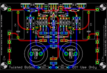
Re: New improved safer version. 🙂
Looks super nice 😀.. Is this a stereo channel or mono ?
Russ White said:Here you go. I actually like this much better! 🙂
Cheers!
Russ
Looks super nice 😀.. Is this a stereo channel or mono ?
Member
Joined 2002
jleaman said:is the inut balanced or single ended ?
Balanced, but I believe you should be able to tie In- and GND together and use it single ended. I will defer to the experts though for the final answer.
Cheers!
Russ
Member
Joined 2002
Russ White said:
Balanced, but I believe you should be able to tie In- and GND together and use it single ended. I will defer to the experts though for the final answer.
Cheers!
Russ
I'd Be interested in 2 boards plus the psu board 😀
Definitely Twisted.
Sign me up for two boards and a psu board. I'll do beta again if you want to take them through the cycle.
Sign me up for two boards and a psu board. I'll do beta again if you want to take them through the cycle.
Originally posted by Russ White
Balanced, but I believe you should be able to tie In- and GND together and use it single ended. I will defer to the experts though for the final answer.
Exactly correct. In fact, you can run single ended in to single ended out if you attach both the -in and -out to ground. If anyone is interested, I put together an arrangement that allows me to switch between SE and Bal inputs and outputs from the front panel in my old CC-CCS-X-BZLS thread. This circuit is very, very flexible, part of the reason I like it so much.
Cheers, Terry
Member
Joined 2002
metalman said:
Exactly correct. In fact, you can run single ended in to single ended out if you attach both the -in and -out to ground. If anyone is interested, I put together an arrangement that allows me to switch between SE and Bal inputs and outputs from the front panel in my old CC-CCS-X-BZLS thread. This circuit is very, very flexible, part of the reason I like it so much.
Cheers, Terry
Ya i like it.. ill have to build one so i can hear the change in sound from my tube pre-amp to this pass labs pre-amp.
- Home
- Amplifiers
- Pass Labs
- My Take on X-BOSOZ