The FETs are very static-sensitive, and they tend to fail shorted. Check continuity between the pins of Q2. Most likely Q2 is dead. You compare these measurements against another FET, but any low resistance readings indicate failure.
It's possible that you have damaged Q2 but IMHO it's more likely Q4.
My first thought is the gate-source voltage on Q2 is a bit high. Ref2 is working properly, but there isn't much voltage across Q4, driving the source of Q2 to1.8V. You're pretty much turning it full on with 4.2V Vgs.
What is the voltage on the gate of Q4? It should be 0. Compare voltages to the other side and figure out what could cause the differences. Here I think either Q4 is shorted or you've got some DC on its input driving it to full on.
Hope this helps.
Thank you for your help guys!
I checked Q2 and Q4, and they seemed fine, but I replaced them anyway. The problem was still there, so I poked around a bit more, until I checked the second half of the circuit, where I found -4V on the Q5 gate. So I changed Q5, and then Q3 also, which fixed the problem.
When I checked the second board, the same issue appeared, so I changed all of those FETs. Everything was working and measuring well, so I left it at that. I connected the last few wires of the controller, and checked the voltages. The same issue came back once more, but on only one of the two boards.
Any ideas on what can cause these repeated failures of the FETs?
Paul
Hi,
I finished the first channel and it works, but R2 and R7 1.5K 3W resistors get really hot, too hot to touch.
I discovered this post later:
So I replaced R5 with 10K (0.25W) and R2 and R7 are hot the same, less than before, but enough hot to be afraid these will burn.
The rails measured on V+ and V- on the preamp are +78.5V and -19.5V.
Any ideas?
I finished the first channel and it works, but R2 and R7 1.5K 3W resistors get really hot, too hot to touch.
I discovered this post later:
Russ White said:
So to wrap things up, the BOM has been corrected and future kits will include the 10K R5 also as Brian said we will happily send 10K resistors to anyone who bought a kit and needs one. Any good 10K metal film resistor should do fine. You could actually use any value from 1.5K to 10K or so. The value is not really critical, just make sure you stay below .15W or so dissipation to keep it running cool. 🙂
So I replaced R5 with 10K (0.25W) and R2 and R7 are hot the same, less than before, but enough hot to be afraid these will burn.
The rails measured on V+ and V- on the preamp are +78.5V and -19.5V.
Any ideas?
They will always get rather warm. Mine idle at about 85C. No problems after more than a year though.

Ok so If I follow the thread correct, the folowing changes were made along the way. D1 is not 1N4004, but 1N5235 6.8VZener, and R5 was changed to 10K. Anything else that came up during the thread? I have skanned through the thread a few times.
I am really looking forward to getting this finished, better late to the party I guess.
Does anybody have the "FINAL" BOM from this project?
Thanks for anyhelp!
I am really looking forward to getting this finished, better late to the party I guess.
Does anybody have the "FINAL" BOM from this project?
Thanks for anyhelp!
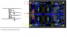
What would need to be done to make the power supply pcb work with 2 center tap secondaries. I have a transformer with several seperate secondary windings. I am not really sure if I am clear on how to connect a transformer in the way I want to.
I am thinking about doing a perf board mock up before trying to connect the power supply pcb. I also just figured someone here could get me going in the right direction.
My quick sketch on what I am thinking:
I see I attached a PCB that is not the final version, however the AC connection do look the same.
Attachments
Last edited:
Brian and Russ, thank you so much for support on these PCB's way past the "fashionable" period.
Answer was that obvious I guess.
Answer was that obvious I guess.
I started one of these when Russ and Brian first started offering them. I believe I was part of the first batch. Anyway, I never finished it. I got the PSU completed and the X-BoSoZ competed except for installing the FET's. When I realized I would need an expensive volume control circuit, I put it on the shelf. Well I have just returned to the hobby and am anxious to complete some of the projects that I left undone. This is one of them. I have looked around and it seems like not many of the X-Bosoz's were built. I see also that Twisted Pair stopped dealing with them. So I'm asking if any of you have built one and if you are still using it. The main reason I got interested in this is because I had just finished an Aleph X and wanted a balanced Pre to go with it. So what do you think? Is this a worthwhile preamp to complete and is there a good attenuator to go with it that is a little less complicated?
Thanks, Terry
Thanks, Terry
Looks like you got your AX working and got the diy bug again?
As for this pre-amp, I will let you know, I have one almost done. I will run with my Mini-A now, and later a diy AX.
As for this pre-amp, I will let you know, I have one almost done. I will run with my Mini-A now, and later a diy AX.
Loved the Pre-amp. Used Russ' switching attenuator. Basic problem I could never resolve was sensitivity to static or transients. Changed the FETs many times .
I have an Audio Alchemy DLC pre-amp. It should handle the switching and volume controls for me.
I would think all the digital stuff would not really be needed, however, pga volume control kits are more common now, and could be had much cheaper than when this project first started.
Steve
I would think all the digital stuff would not really be needed, however, pga volume control kits are more common now, and could be had much cheaper than when this project first started.
Steve
What are you using for the attenuator?
Hi,
I´m still using my X-BOSOZ into a pair of Aleph-X and build another one for a friend.
In my amp I´m using a balanced attenuator (is somewhere in the Borbely papers) which is quite simple (a 24-step switch and 46 resistors) but you can´t buy it ready made (at least I didn´t find a supplier). You can have a nice low output impedance with these but it will be dependend on the volume setting.
The other I build with a remote controlled volume control from Dantimax (for balanced amps)
William
- Home
- Amplifiers
- Pass Labs
- My Take on X-BOSOZ