You are back
Good to see you again Terry (and Bob Ellis too)!
Your progress reminds me of myself. Gaining 2 steps forward but then 1 step back, you fix the problem, go 3 steps forward and then 1 back, until you finally get it all done. Its a pain right!
FYI, I also was disappointed by the Aleph sound (I had a commercial one, a-30 I think) as it just seemed weak and lifeless. Not politically correct to say here obviously but there you have it.
This preamp though sounds really good, and I am happy with it. I would encourage you to finish it.
The construction problem is the potentiometers for volume control. You really need a quiet 4 gang pot to control the volume on both channels at the same time since each channel has 2 pots by itself. Not sure of a good part to use....I think the original Pass schematic has 10K pots but people use the more common 100K instead and I'm not sure how or if this affects anything. I recall trying to find a 4 gang of the original spec unsuccessfully in the past. Just saying.
Anyway good luck and happy to see you are still around.
Hi lGreen,
Really good to hear from you. As you probably remember, you sent me the A-X boards. I sure wish I could get it to sound the way everyone else does. They rave about it. Mine is the wimpiest sounding of all my amps.
I think my problem with this preamp is the spade connectors. They are so close together that I keep shorting them trying to work on it. Those big caps hold so much energy on both the PSU and the Pre. I think I have them drained but then something touches and POW, I've blown a zener or FET. I wanted to save my shielded female spade adapters for the final setup so I made some patch cables with unshielded connectors. That has proven to be my undoing. I have new parts coming. Once here, I will pony up for some extra shielded connectors so I can work on this thing without blowing things up. 🙁
Blessings, Terry
PS, I ordered a "Balance XLR DACT Type 21 Stepped Attenuator Potentiometer 10K" from Ebay. I am hoping it will do the job for this Preamp.
Attachments
Last edited:
Curious what speakers you had with your A30. Low powered single ended class A and low impedance loads don't play well together.
Although it's preferable to have the attenuator at the output you can put it at the input. Most modern sources can easily drive a 20K load. Then if you like the sound you can decide if you want to try an output attenuator instead.
You can also set it up for no gain and use it as a unbalanced to balanced converter. I'm planning to use this circuit in that role. I have a couple sets of Kari's boards and just found 4 2SK389s and 20 109s and 74s that I thought i lost in a move. Time to rework the boards to use jfets and get started on Aleph J and F5 projects. 😀
So I went to the shack today and picked up a bunch of shielded female blade connectors. I will be making up some more jumpers. As soon as my parts get here I'll replace them and get back to you. Hopefully with good news. 😀
I just received the transformer for my B1 Mesmerize. Now I know why you guys weren't crazy about the PE transformer some of us bought. This thing is tiny by comparison. I may switch out the PE before I'm done.
I just received the transformer for my B1 Mesmerize. Now I know why you guys weren't crazy about the PE transformer some of us bought. This thing is tiny by comparison. I may switch out the PE before I'm done.
I'm thinking of replacing the large transformer that I had purchased for this and buy a couple of small ones. Would these two transformers be suitable?
Antek - AN-0215
Antek - AS-0528
The 15V in parallel for the - rail and the 28V in series for the +rail.
Thanks, Terry
Antek - AN-0215
Antek - AS-0528
The 15V in parallel for the - rail and the 28V in series for the +rail.
Thanks, Terry
OK, I got it running. I replaced the two 33V zeners in one of the power supplies. It is putting out about 3V less than the other one. Probably not a huge deal. I replaced the 6.3V zeners in both preamp boards. I had removed one of the 27R resistors last week in an attempt to get it to work with a 9.1V zener. Didn't have another so I stuck a 33R in. Seems to be working OK. The + rail seems to be running a couple volts higher but the signal looks clean.
I don't have a volume pot yet so I just played it using my Zune so I could control the volume. Only one problem. I have a pretty good ground loop some where. Of those of you who have completed one of these, How did you do the ground. Right now I just have the grounds attached to the individual boards with no star ground and no earth ground. No case of course. Anyway, there's no hum if I play one channel at a time.
One other thing. Twice now the PS boards have burned a trace between the AC power spade and the rectifier diodes when powering up with empty caps. If I bring it up with the variac it is OK. Once the caps have been filled, subsequent startups are not a problem since the caps never completely empty again. Actually, the first time this happened, it took our a couple 4004's.
Blessings, Terry
Without a star ground you are connecting the two channels randomly through your interconnects causing your ground loop hum. Make a proper star and I bet the issue goes away.
The channel with 33r is running with slightly lower bias current. If you hear a difference it might be worth fixing.
Not sure why you're burning traces. If theres not a fault downstream, did you use particularly low esr caps and a transformer with great regulation? Try measuring the input current when there is nothing connected to the PSU. Is anything getting very hot? Are there bleeder resistors?
Maybe try 10R 1W in series with the AC to limit the inrush current without seriously reducing the supply voltage.
Thanks Bob,
Yes, I intend to try star ground today. I can't hear any difference between the two. The only reason I even noticed was when I but both channels on the scope and overlayed the two signals. The one with the 27R has slightly more output. I measured the output with a DMM and with a 1.4V input, the stronger one puts out 2.4Vac and the weaker 2.35Vac. I'm not sure you can hear that playing music through a Zune.
As for the burned traces, the first time it happened was with only the PS connected to the transformer. The PS board had sat for 8 years. Like a dummy, I didn't hook up the variac and reform it, I just plugged it in. It took out the traces between the diodes and the spade connectors on the + rail as well as a couple of the 1n4004s. After I replaced the diodes, I soldered in a couple jumper wires and haven't had a problem again until yesterday when I hooked up everything at once. I had both PS hooked to the transformer with their respective preamp boards hooked up to them. I had recently drained all of the caps in both PS and pre boards because I didn't want any issues while hooking up all the spade connector leads. The weird thing is, I even had the transformer plugged in through a lightbulb. The moment I switched it on, the bulb glowed for a couple seconds as you would expect and then went out but I heard and saw a spark emit from under one of the PS boards. I shut it down and under inspection, the trace had opened right next to the solder joint of one of the spade connectors on the board that hadn't been repaired before. As I'm typing this I am wondering if maybe that trace had become weakened from continuous plugging and unplugging from the spade. They do get pretty good workout each time you have to unplug.
Also, I don't know if you saw my earlier post about transformers. I would like to go with a couple smaller transformers rather than this big one. What vA is required for one of these? Will it work properly with two 25Va transformers, a 15V and a 27V, each hooked in series?
Thanks, Terry
25 VA ought to be fine. Thinking about it, I suspect since you are doing this on the bench maybe something was shorting somewhere.
Hi Bob,
Thank, I'll order a couple small transformers.
The star ground did the trick. Listening right now. Sounds nice and clear. Hard to tell the fidelity since it's playing out of the earphone jack from the Zune but actually is very encouraging.
Pretty sure the last trace issue was due to mechanical flexing from numerous plugging and unplugging of the spade terminals. I will check all of them once I am ready to install it into a case. Thanks again for all your help.
This will be used for balanced signal duty. Still hoping to get my A-X sounding right.
I am also building a B1 Mesmerize for use with some of my amps. Just waiting on those elusive Jfets. 🙁
Thanks again for all your help.
Blessings, Terry
Hi Guys,
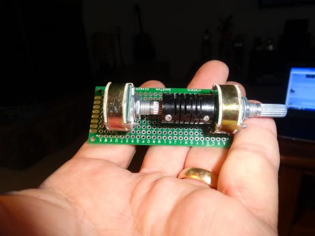
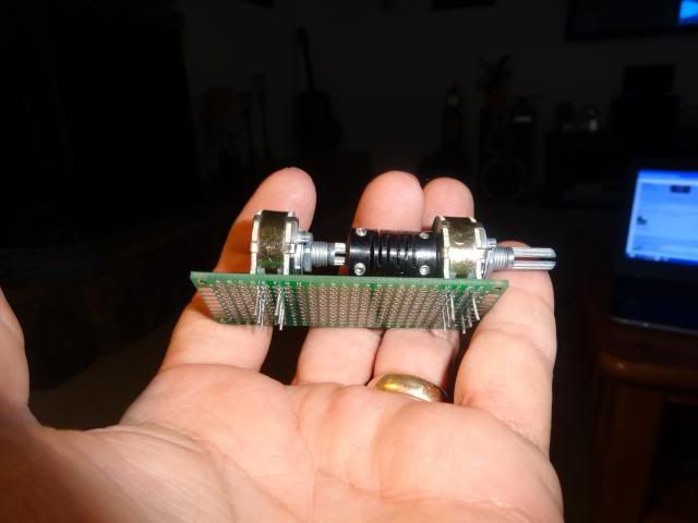
I received my attenuator today and it dawned on me that I haven't a clue how to hook it up. Here are a couple pictures of it. They ship it plugged into a nice little patch board which should come in handy.
I plan to hook it up between the boards and the output jacks so any help will be greatly appreciated.


I take it you are attenuating a balanced signal, since theres two stereopots connected. Put the pot on zero and measure between the center pin, which is usually wiper and left or right pin in line with the wiper pin. The one that gives the highest resistance is signal in. Wiper is signal out, the third to ground. I would have used one pot per channel, i e both signal and inverted signal since they are more likely to match. But that you can measure.
Do the same for the other channel on the other pot.
Do the same for the other channel on the other pot.
Last edited:
OK, I tested them. If I turn the pots completely clockwise and connect the com wire of the DMM to the center post, I get 000R4 on pin #1. Pin #3 shows 10K08.
Now so I'm clear, I have 3 outputs on each channel. OUT- GND OUT+. Weird, this is the first time I noticed that the inputs are reversed, IN+ GND IN-.
Anyway, The GND out would connect to the two #1 pins of say the front pot and the +/- outs would then connect to the two #2 pins.Then the two #3 pins would feed the XLR? Sound right?
Thanks, Terry
Last edited:
The #2 pin is the wiper, correct? When you turn it counterclockwise it is 0R to pin 3, correct? That's the one that connects to your XLR. Pin #3 connects to your XBOSOZ ground and #1 to the XBOSOZ output (unless you want clockwise to be maximum attenuation.)
I'm sorry Bob, I just read my previous post and I said it wrong. It should have said "counter-clockwise". With the pot all the way counter-clockwise, Pin #1 reads 0R and Pin #3 reads 10K. Full clockwise, pin #1 reads 10K and Pin #3 reads 0R. This is with the other lead connected to pin #2 (center).
BTW, this is a step-attenuator not a pot.
Thanks, Terry
BTW, this is a step-attenuator not a pot.
Thanks, Terry
OK, then pin 1 to ground, 3 to XBOSOZ output, pin 2 to XLR. A stepped attenuator should mean better tracking than a couple of random pots.
- Home
- Amplifiers
- Pass Labs
- My Take on X-BOSOZ