active load looks worthwhile to try;
but0overall ,I'm not sure that origigi NS10 will sound better than NP's "from memory " version....
anyway-somebody can try this in vivo?
steen,AKA Lucky Luke ?

symetricall and twice 25V looks more promising than plain 25V version,with lotsa elcos in signal route.....
anyway-tis is my (old ) thinking about PS (this time for single rail version) :
prereg for all stages:
but0overall ,I'm not sure that origigi NS10 will sound better than NP's "from memory " version....
anyway-somebody can try this in vivo?
steen,AKA Lucky Luke ?
symetricall and twice 25V looks more promising than plain 25V version,with lotsa elcos in signal route.....
anyway-tis is my (old ) thinking about PS (this time for single rail version) :
prereg for all stages:
Attachments
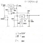
local reg for each stage:
I need also data for current consumption of servo IC-which one we will use?
741?
TL07x?
anyway- two servos can be in one chip (TL072 ?) and one dedicated shunt reg can be used for that chip,with adequate bigger resistor in 317 CCS.........
I need also data for current consumption of servo IC-which one we will use?
741?
TL07x?
anyway- two servos can be in one chip (TL072 ?) and one dedicated shunt reg can be used for that chip,with adequate bigger resistor in 317 CCS.........
Attachments
Choky,
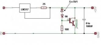
This pre needs the best PSU we can through to it. The servo needs a separate reg or sub reg to it (12 - 15 V).
Couldn't we try some of the nice shunt ideas from the BT thread?
This pre needs the best PSU we can through to it. The servo needs a separate reg or sub reg to it (12 - 15 V).
Couldn't we try some of the nice shunt ideas from the BT thread?
apassgear said:Choky,
This pre needs the best PSU we can through to it. The servo needs a separate reg or sub reg to it (12 - 15 V).
Couldn't we try some of the nice shunt ideas from the BT thread?
maybe I miss something,but I can't see nowhere what exact voltage is for LM307.....
just remember that positive input is referenced to 25V/2.....
anyway,307 is same jobie as 107 ,and that is +/- 22V supply capable chip....so I presume that here 307 is feeded from same rail as rest of circuit
maybe I wasn't clear enough-I just proposed that one double chip can be used for two channel servo (one double for RIAA and one double for line stage) ; and one local reg for one double chip....
I must confess that I didn't follow BT thread to closely........with all respect- that thread is somewhat messy and confusing from time to time....with tiny spice of snake oiling ........
besides-in last schmtc (http://www.diyaudio.com/forums/attachment.php?s=&postid=872424&stamp=1142694768
R10=18K2
and R11 is just 330E
looks muuuuucho to me?
origigi NS10 claims adjustable gain up to 20 db...........
R10=18K2
and R11 is just 330E
looks muuuuucho to me?
origigi NS10 claims adjustable gain up to 20 db...........
anyway-whatever PS we use, I would stay with +/-25V version and use Q4 and rest of dedicated parts instead 2K7 in output......
looks less complicated
servo?
maybe for purpose of trowing out output cap
looks less complicated
servo?
maybe for purpose of trowing out output cap
LM307 is only +-18V max, just checked the spec.
Positive input is a comparated value which should be what you say, arround 12.5V which again is compareded in the opamp to the near same output 12.5V. Really don't understand the purpose of this opamp, the circuit did perform without it. It only mantains a relative bias to the input base related to the output. Will this provide a better performance to the stage? If the Master say so, it should.
Can someone enlight me with the function of this?
As you say Choky, the servo does not provide the benefit of getting rid of the output cap as does the SL10. So why should we have the servo for?😕
apassgear said:As you say Choky, the servo does not provide the benefit of getting rid of the output cap as does the SL10. So why should we have the servo for?😕
as I see it-just maintaining relative symmetry (25V/2 on output cap)
as I see it also-we can get rid of output cap with that servo,if we use symmetric supply
but- it will sounds better........?
regarding twice 18 volts for 307- that means you can use up to 36V for little critter
If we use a double rail supply we should look closer to the SL10 stage which in my opinion should be better, no signal caps, less pasive components, CCS, CMNR...
Spec though say: max DCV out = 10 mV which seems quite high for a preamp and would require an AC coupled amp or to add a cap at the output (more likely). Once again the servo would be useless?
Spec though say: max DCV out = 10 mV which seems quite high for a preamp and would require an AC coupled amp or to add a cap at the output (more likely). Once again the servo would be useless?
I wont start building another version of this preamp before I have heard back from the guy with the original NS10. If I get my hands on the original, I will work on restoring it with audiophile caps and pots and so on. Just so you dont sit around waiting for Lucky Luke😀 If he decides not to sell it to me, I will be ready for some prototype'ing🙂 He promised to call me sometime this week🙂anyway-somebody can try this in vivo?
Steen🙂
Don’t worry Steen, anyway its fun.
Hope you twist the hand to that happy NS10 owner and return home with a precious box, 😀
Hope you twist the hand to that happy NS10 owner and return home with a precious box, 😀
NS10 reverse design attempts
In my opinion if one changes the NS10 concept in a major way like going to +/- power supplies, it is not an NS10 anymore, it is better called an NS10 variation. That means, you keep the basic topology, but enhances it to see how far, how good, this basic concept can be made.
A reverse engineering should try to keep everything "as is" ("as was") including +24 V, but maybe changing the opamp to some other available. (But as crappy as possible.)
RK
R-K,
I agree with your comment.
We did depart from the original last time and think it was not a wise move. For one example, I don't remember who's idea was to add a base resistor to Q3.
My concerns about the servo is, most probably, that I don't fully understand its purpose. Would like to know though.
I agree with your comment.
We did depart from the original last time and think it was not a wise move. For one example, I don't remember who's idea was to add a base resistor to Q3.
My concerns about the servo is, most probably, that I don't fully understand its purpose. Would like to know though.
NS10 servo
I would expect the purpose of the servo to be to hold the output at Vcc/2 = 12 V DC. Not 10 V or 14 V or whatever. Still, at it is at an offset from 0 V DC, it needs coupling capacitors. One could of course wonder if i is necessary as a capacitor is needed anyway. But it is worthwhile to keep the feedback at to the input at midpoint (=12 V DC).
I would expect the purpose of the servo to be to hold the output at Vcc/2 = 12 V DC. Not 10 V or 14 V or whatever. Still, at it is at an offset from 0 V DC, it needs coupling capacitors. One could of course wonder if i is necessary as a capacitor is needed anyway. But it is worthwhile to keep the feedback at to the input at midpoint (=12 V DC).
Yes, it will hold Vcc/2. I still wonder thou if this has any effect soundwise. The Master is a clever guy so it should. Maybe it has to do with the FB coming to the emiter.
I would think the circuit is designed to work with 0 at Vcc/2 so an offset from that would move the operating points away from the ideal. That is, a signal at the base of Q1 should be centered at 12 V, not 11 or 13 or whatever, for the circuit to behave as the master wished.
Ok, now I got it, the base of Q1 needs biasing and this is the most elegant bias that could be have, it will always track, as you say, at Vcc/2.
Being a double rail, our previous effort, didn't need a bias, we just sitted it at ground level.
Being a double rail, our previous effort, didn't need a bias, we just sitted it at ground level.
apassgear said:Ok, now I got it, the base of Q1 needs biasing and this is the most elegant bias that could be have, it will always track, as you say, at Vcc/2.
What it also does, is allow you to use different feedback resistor values, as the "servo" acts as a dynamic DC feedback path. If you used a method for bias that didn't track, you would have to find a value of feedback R that gives 1/2 Vcc on the output. Any change in resistance, and the bias and output voltage changes.
jD
- Status
- Not open for further replies.
- Home
- Amplifiers
- Pass Labs
- My Take on Threshold NS10