the quads can be used to give doubles and singles.
The problem at the moment is the 40 or so that want a +ve regulator only.
How do we satisfy that requirement cheaply?
If scoring is cheap, then quads could be the easiest and cheapest way to buy the PCBs. But what do we do about the +ve only guys?
If you split the order into single +ve and single -ve, then you have two smaller orders. That pushes the cost up for the rest of us.
If you can get the cost down to the CeToole, you have potentially >1000 regulators to source and sell on.
I'm thinking that there are two kind of people: those who need only the +ve version, and those who need both -ve and +ve. I can't think of any project that uses only -ve. So most sense would be to order a whole bunch of +ve boards, and a whole bunch of dual rail boards.
Andrew, what do you mean about the cost of the cetoole reg? The reason I don't see hundreds of people interested in this regulator is not the high price, since none has been set.
Edit: I should add, there are two ways you can get this regulator for the price of a few coffees:
1) You make your own boards. It's easy. I've done it. It works. I can guide you and help with that.
2) You're at at time in your life that money is very tight. Then let me know privately.
Last edited:
The reason I don't see hundreds of people interested in this regulator is not the high price, since none has been set.
No, it's that they dont know how good it is 😀
He he 🙂 Do you know that I've tried very hard to make the cetoole regulator work? Look back in the development thread, I really did put a lot of work into that, and just... the design had some trouble. Couldn't make it as stable as I wanted it to be. Then I saw this huge GB started on a design that wasn't even finished. It freaked me out in a way, because I couldn't understand the phenomenon. It's probably fixed now, I haven't kept track of the latest developments.
The current thread's CCT concept works smoothly in many guises. I am in good experience to know it.😉 Then you invested much time and iterations, parts research, trial and error, measurements, did your very own board design and proofing. So you took V1 concept to V2 performance and stability standard. I feel that I maybe would not have shown this kind of dedication so to take it there, if I was set to. Thank you for highlighting the concept to its rightful elevated performance standard. I guess that your work should be counted in the price you are going to set for the boards, its in no way just a matter of resin sqInch and etched cooper thickness IMHO. Good work.
Salas, you're too nice. But you know what's involved in making these so you speak from experience. If anyone should get something back from the hours on end of work, plus hours on end of customer support, it's you!
So I tried some quotes from pcb fab people and guess what? The cheapest way was to get the boards individually done, not several circuits on one bigger v-scored board. Andrew, are you listening? The difference in price was not large, but with the v-scored boards there is extra work involved in separating the circuits for those who want them separate. So, there goes that myth.
So I tried some quotes from pcb fab people and guess what? The cheapest way was to get the boards individually done, not several circuits on one bigger v-scored board. Andrew, are you listening? The difference in price was not large, but with the v-scored boards there is extra work involved in separating the circuits for those who want them separate. So, there goes that myth.
received logic level MOSFETs and assembled new board.
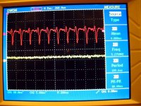
Picture without output cap, oscillations with 88 mV peak-to-peak

Output cap 3.3uF MKP Vishay

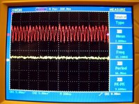
Zoomed trace, final version.
Output cap 47uF Panasonic FC + bypass 4.7uF MKT EPCOS
http://www.diyaudio.com/forums/attachment.php?attachmentid=150751&stc=1&d=1261181853
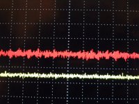
Bottom trace (white-yellow) is noise floor.
Output wires & sense wires cut to 3 cm.
I can confirm that placing output cap at load introduced some oscillations, better to keep output cap close to MOSFET.
Tried different caps, good results with Panasonic FC and FM, Elna Silmic, Oscon. I think this cap should be low ESR type.
Another bypass with 100nF or 220nF and oscillations returns 😛
Picture without output cap, oscillations with 88 mV peak-to-peak
Output cap 3.3uF MKP Vishay
Zoomed trace, final version.
Output cap 47uF Panasonic FC + bypass 4.7uF MKT EPCOS
http://www.diyaudio.com/forums/attachment.php?attachmentid=150751&stc=1&d=1261181853
Bottom trace (white-yellow) is noise floor.
Output wires & sense wires cut to 3 cm.
I can confirm that placing output cap at load introduced some oscillations, better to keep output cap close to MOSFET.
Tried different caps, good results with Panasonic FC and FM, Elna Silmic, Oscon. I think this cap should be low ESR type.
Another bypass with 100nF or 220nF and oscillations returns 😛
Attachments
Good info. What load? Roughly what was the ripple on the input? 5V output?
The last image shows ripple close to the noise floor. What would you estimate it to be peak-to-peak?
stormsonic, did you receive the email I sent you a few days ago?
The last image shows ripple close to the noise floor. What would you estimate it to be peak-to-peak?
stormsonic, did you receive the email I sent you a few days ago?
Yes, received email today 😛 (sent Dec. 15th)
I think problem was in different MOSFETs (IRFBC40 & CEB703AL).
Input 12V, shunt current set to 500 mA. Output 5V, load 100 mA (resistor).
Look at 2nd picture, lower left corner. Grid is 5 mV, output ripple 3.6 mV peak-to-peak.
I think problem was in different MOSFETs (IRFBC40 & CEB703AL).
Input 12V, shunt current set to 500 mA. Output 5V, load 100 mA (resistor).
Look at 2nd picture, lower left corner. Grid is 5 mV, output ripple 3.6 mV peak-to-peak.
Thanks stormsonic. Now let's get to business. 3.6mV peak-to-peak is too much 😀
The images I showed earlier were sub 30-40 uV peak-to-peak. This has happened with about 15cm or output wire (both output and sense). Both latest pcb prototypes same performance. And I don't cheat.
There might be something off with your implementation?
The images I showed earlier were sub 30-40 uV peak-to-peak. This has happened with about 15cm or output wire (both output and sense). Both latest pcb prototypes same performance. And I don't cheat.
There might be something off with your implementation?
Can't be. The Simpler Simplistic HV which is ultra basic was shown with 1mV on an analogous TFT screen scope, long outs, no remote sensing, next to heater wires and valves, with rudimentary CRC input. V2 LV should show just thin line in a digital source environment. Is the Vref filtered with 220uF in your implementation Stormsonic? Or it may be the GND.
or the measuring bridge is tapped into the wrong locations or maybe the bridge is broken into separate sections.
or the measuring bridge is tapped into the wrong locations or maybe the bridge is broken into separate sections.
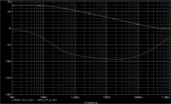
No; in this design, it's most likely the result of a max 30 degs phase margin. Under such circumstances, the output cap parasitics (L, R) and wiring are deciding the stability.
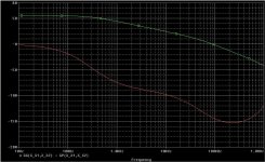
To avoid any idiosyncrasies, I'm not going to compare this design to other solutions but the Salas regulator.
See below; the Salas regulator has significantly larger open loop gain, much unity gain loop frequency and a very large phase margin; it is unconditionally stable and has a good (although not perfect) frequency (because of the decent bandwidth) and transient (because the relatively small phase dip) response.
It is certainly funny to compare these results with the subjective opinions Yeah, the virtually unstable design "sounds better"
See below; the Salas regulator has significantly larger open loop gain, much unity gain loop frequency and a very large phase margin; it is unconditionally stable and has a good (although not perfect) frequency (because of the decent bandwidth) and transient (because the relatively small phase dip) response.
It is certainly funny to compare these results with the subjective opinions
Yeah, the virtually unstable design "sounds better" Attachments
I thought I was on your ignore list syn08. What, has the season opened on little me? 🙂
You're not saying anything we've not been saying for a while. Having to be careful with the layout and wiring, is it not a trivial consequence of dealing with high gain at higher frequencies in such a design?
I personally have said in many threads that the salas v1 design has, among many other positives, an unconditional stability.
I've tested a few different builds of this design, of which two were on my pcb layout and the rest air sculpture, so to say. None oscillated.
As for subjective views on sound, please don't pollute this thread with your derisive "" at anyone who has an opinion. We all know how much you enjoy condescending us the lesser ones, but please, keep it technical.
You're not saying anything we've not been saying for a while. Having to be careful with the layout and wiring, is it not a trivial consequence of dealing with high gain at higher frequencies in such a design?
I personally have said in many threads that the salas v1 design has, among many other positives, an unconditional stability.
I've tested a few different builds of this design, of which two were on my pcb layout and the rest air sculpture, so to say. None oscillated.
As for subjective views on sound, please don't pollute this thread with your derisive "
" at anyone who has an opinion. We all know how much you enjoy condescending us the lesser ones, but please, keep it technical.the Salas regulator has significantly larger open loop gain
Oopsy daisy! I just noticed this. the Salas regulator does indeed have larger phase margin, but it does not have a higher open loop gain. Your analysis is flawed.
Phase margin, phase shmargin...
Here everyone, if you want to treat your ears to a special sound that even syn08 can't measure 😀 go to The Adler Trio Site - ùìéùééú àãìø - îôåçéåú and click on English, then click on Music, then browse (click on right arrow) until you get to the album named "The Adler Trio and Friends!" Play the thirds song, named "Flambee Montalbanaise" 😉
You need a good system to hear the richness of that sound! At least a pair of good headphones will do 😀
unable to edit wiki?
Hi folks,
First; ikoflexer, thanks for the effort to develop this supply. I have been following this tread some time and have decided I would like to build this supply for my guitar hi-gain pre-amplifier stages wich are never quiet enough.
I have been trying to add my name to the group buy wiki but I get this message all the time:
"You cannot edit this article at this time because there is currently a previous edit awaiting approval."
My activity in the electronics department have been sleeping for about 15 years and the landscape has changed quite a bit. I am a bit wondering about where to get the parts. Maybe the other dutchies in this tread can fill me in? Or maybe we can start a parts group buy?
Hey, cool! But I get the same error. Probably something wrong with the forum at the moment? Let's wait a bit, I'll contact the forum people about it a little later.
The parts shouldn't be hard to find. Have a look locally in your town see what you can find. That'll save on shipping vs. buying online.
The parts shouldn't be hard to find. Have a look locally in your town see what you can find. That'll save on shipping vs. buying online.
Hi folks,
My activity in the electronics department have been sleeping for about 15 years and the landscape has changed quite a bit. I am a bit wondering about where to get the parts. Maybe the other dutchies in this tread can fill me in? Or maybe we can start a parts group buy?
Dick Best, Conrad, Bakelaar-Julianadorp and Hajé are some shops in Holland with online facilities (use google). Good strategy is also to fill in the part's type number in the search function of Ebay.
syn08 said:It is certainly funny to compare these results with the subjective opinions
...and I can't help being amused by those who can look at a circuit or simulation, neither of which have any good relation to reality anyway, and then decide which sounds best.
Unless they have such good eyes...
- Status
- Not open for further replies.
- Home
- Amplifiers
- Power Supplies
- My take on a discrete shunt voltage regulator