Hi telstar. First, the schematic has a bad mistake. The point in between the two CCS mosfets is connected directly to ground.
The idea of cascode CCS has been proposed quite a few times. There are reasons for which I don't want to include it in the regulator circuit, but I'm not saying you or anybody else should not use it; I would definitely stay away from using a zener there, unless you want certain noise.
IMHO, all my analyses show that there is a significantly greater benefit from using a good cap multiplier/gyrator circuit just before the regulator.
Regarding a jfet of higher voltage in that position, you can do it, but it helps nothing. The jfet does not see anything near 30V in that position, so it's safe.
I will send you a pm with my email.
Hi telstar. First, the schematic has a bad mistake. The point in between the two CCS mosfets is connected directly to ground.
Ops, will fix it!
The idea of cascode CCS has been proposed quite a few times. There are reasons for which I don't want to include it in the regulator circuit, but I'm not saying you or anybody else should not use it
I have just re-read the last 3 pages of this thread and i'm starting to understand more, and I think I understand your position.
I would definitely stay away from using a zener there, unless you want certain noise.
I agree. Just another led then, or should i scrap it?
IMHO, all my analyses show that there is a significantly greater benefit from using a good cap multiplier/gyrator circuit just before the regulator.
Thanks, will keep in mind. I'm going to put some sort of prefiltering, and go with your 5c/5d circuits as is (except values)
Still on the brainstorming stage 🙂 As usual, is a matter of costs/benefits.
I would use a choke if cost no object. With a circuit with already good PSRR (this i know for sure), maybe i dont need more than a couple decent caps, per rail (i'd rather not cap multiply if the values are in the 1000-4700uF range).
Regarding a jfet of higher voltage in that position, you can do it, but it helps nothing. The jfet does not see anything near 30V in that position, so it's safe.
For my application, I'm in need of 17-20V output, not 5V and the like, but the amperage is still pretty low. Still safe to use the 2n3819 or i should look for a stronger jfet?
I will send you a pm with my email.
Got it, thanks.
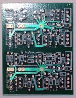
The negative version layout is finished finally, having same size as the positive, 3x2 inches. Now it only remains for me to build a prototype and then order a number of them.
Question to you all: do you prefer them positive+negative on the same board, or separate boards positive and negative?
Question to you all: do you prefer them positive+negative on the same board, or separate boards positive and negative?
Check for pricing - i would prefer both together as I m planning to use both for my application
kannan
kannan
Question to you all: do you prefer them positive+negative on the same board, or separate boards positive and negative?
I would prefer two boards for better separation, but it's nitpicking.
The negative version layout is finished finally, having same size as the positive, 3x2 inches. Now it only remains for me to build a prototype and then order a number of them.
Question to you all: do you prefer them positive+negative on the same board, or separate boards positive and negative?
Hi Iko!
I would prefer separate boards since I only need the positive rail version.
Karsten
ok guys, it's hard to make everyone happy. To get a good price I'm going to order 100pcs negative and 100pcs positive. Some of them will be for my projects and the rest goes to whoever is interested. I'll try to get the lowest price possible BUT I will not make the boards too thin or cut corners that way. 2oz copper and 0.063in thickness sound good to me. The main current pathways will be double 2oz so the boards could be used for small power amps. More than 2oz can be problematic to really get it from some manufacturers so I don't even want to complicate our existence with it. It's easy enough to thicken the conduit with a separate soldered wire if you want to use is for some crazy power amp.
I am planning to donate to diyaudio myself from this project, that is, from myself. But I will not force anyone to do it. I don't believe in forced charity. If any of you want to chip in a little for diyaudio making it possible for us to communicate and get this going, then you can mention $x for so and so and it will go there. That will happen when you pay for your boards.
If any of you are struggling students or struggling financially in any way but would like to get some boards mention this in private email when the time comes and I will try to help you.
I'll get back to you guys with more info about the price, time, etc.
Iko, my proposal, if possible:
- each PCB board should hold two independent regulator circuit. Each circuit can be set as positive or as negative version.
With that arrangement, you can have two positive versions, two negative versions or one positive and one negative version.
If anyone need only one regulator, PCB can be cut in half.
Production costs will be reduced.
Very clever solution for SupperTeddyReg PCB, pic bellow
Attachments
It's a good suggestion stormsonic, but there is a technical problem. The negative STR board is done so that it uses the same layout but complementary parts (pnp instead of npn, p-channel instead of n-channel). Now you can see the obvious advantage: you can use the same board for positive and negative. There is a disadvantage though. The negative version will have quite different specs (line and load regulation for instance). Now this does not happen when the negative regulator is designed the way I did it. So you can expect the negative and the positive rails to have specs that are close to each other. The other advantage is that you can use the same type devices on both rails. However, the positive layout cannot be the same as the negative layout.
To get a good price I'm going to order 100pcs negative and 100pcs positive. Some of them will be for my projects and the rest goes to whoever is interested. I'll try to get the lowest price possible BUT I will not make the boards too thin or cut corners that way. 2oz copper and 0.063in thickness sound good to me. The main current pathways will be double 2oz so the boards could be used for small power amps. More than 2oz can be problematic to really get it from some manufacturers so I don't even want to complicate our existence with it.
It sounds good to me. I was going to ask to make it 2 oz copper 🙂
It'd be nice to have a positive and a bipolar version of the board.
Question: I suppose that if you tie the 0-volts of the pos.-board and the neg.-board together you have your bipolar version ?
Very interested in trying this out as well, and would like a couple of +/- boards. I'll keep an eye out for when they are ready.
To get a good price I'm going to order 100pcs negative and 100pcs positive.
Sounds like a plan. 😎
Having separate boards makes it more flexible.
Still I think it's wise to order more positive than negative boards (perhaps 150 positive - esp. if there is a price break with the PCB factory).
The negative boards will always be paired to positive ones while there'll be some projects that need only positive boards.
Hi Ikoflexer,
I prefer separate boards, ok 2oz copper. If finally is a GB I am interested to buy some pcbs positive & negative.
merlin el mago
I prefer separate boards, ok 2oz copper. If finally is a GB I am interested to buy some pcbs positive & negative.
merlin el mago
buying as a four circuit PCB will be much cheaper.
Do we have a volunteer to cut the PCBs in half or quarters?
Do we have a volunteer to cut the PCBs in half or quarters?
OK guys, I'm going to look into creating a wiki with all the choices we have so far. Then I get an idea of what the distribution of choices is and then we'll make a decision. I'll be back with a link to it.
buying as a four circuit PCB will be much cheaper.
Do we have a volunteer to cut the PCBs in half or quarters?
AndrewT,
If needed I will cut the PCBs
merlin el mago
Last edited:
- Status
- Not open for further replies.
- Home
- Amplifiers
- Power Supplies
- My take on a discrete shunt voltage regulator