Hifinutnut, you're back with a vengeance eh?!? Well done, I'm glad you got it done. BTW, with a larger R7 the current through the mini-ccs will be smaller, and then turning R2 will not result in such a large change in the main-CCS current.
Thank you for all the valuable observations. A lot of people can benefit from them.
I'd like to apologize to everybody for the delay in getting the neg-rail pcb done. Right after Christmas I got some sort of nasty flu and been mostly in bed feverish. Hope to get it done soon, then test it well, and then finally do a last call for the group buy.
I hope you will get better soon.
Before finding the C-Multiplier, I am now thinking about using the LM317/337 pre-regulator after the bridge. It is followed by LRC circuit, i.e. PreReg - LRC. This will replace the existing C-LRC, which has been proven better than C or CRC. Effectively, the pre-reg only replaces the first C.
I know how bad the LM317/337 sounds by itself. But surely the noise can be removed with LR following it?
Hifinutnut, you're back with a vengeance eh?!? Well done, I'm glad you got it done.
No it is not done yet. I am learning from each build. I will rebuild it with thicker tracks (I have realized this only in the last build with all those funny resonances and when I compared to your PCB layout), a higher voltage cap shunt across the Vref in the CSS (the lower impedance works), better placement of the output cap, and re-introduce the input cap (2,200uF), and optimize the heatsink use (only need a smaller heatsink for the CCS), etc.
I found the sound became smoother after 2 days playing. This points to the burn-in of the only electrolytic capacitor across Vref. So again this points to the fact that that capacitor can influence the sound (I thought this cap would have minimal effect).
Thanks, me too!
I got something that might be of interest to you, regarding pre-filtering. stormsonic showed me some nice result; he implemented a well known pre-filtering circuit, which is basically a couple of c-multipliers in series, and then compared it with the regulator. The regulator alone had better line rejection than c-mult alone. c-mult in series before the regulator had a tiny bit better line rejection than the regulator alone. So little was the benefit that he didn't think it wasn't so much worth it to put extra effort into the pre-filter. I wish he could say it himself so I don't make any mistake about it. It came to me as a bit of a surprise because I expected that a design specially made for line rejection only, like that which stormsonic tested, would be a little bit better then the regulator at it. Note I did not say output impedance. That circuit is no match at that. It turns out that the regulator is better even at line rejection. I thought it was a pleasant surprise.
I got something that might be of interest to you, regarding pre-filtering. stormsonic showed me some nice result; he implemented a well known pre-filtering circuit, which is basically a couple of c-multipliers in series, and then compared it with the regulator. The regulator alone had better line rejection than c-mult alone. c-mult in series before the regulator had a tiny bit better line rejection than the regulator alone. So little was the benefit that he didn't think it wasn't so much worth it to put extra effort into the pre-filter. I wish he could say it himself so I don't make any mistake about it. It came to me as a bit of a surprise because I expected that a design specially made for line rejection only, like that which stormsonic tested, would be a little bit better then the regulator at it. Note I did not say output impedance. That circuit is no match at that. It turns out that the regulator is better even at line rejection. I thought it was a pleasant surprise.
Thanks for that information. While I accept that finding to be true, there are so many factors related so I am not sure if all things are conclusive. What I mean is that it does not hurt to even increase the line rejection.
While RF parts are being used, I found chaning the raw supply C (9,900uF) to 3,300uF - 470uH + 1R - 6,600uF did improve the sound. The improvement is very obvious. This was also seen in my oscilliscope. Without it, the line around 200k region (which points to about 2MHz) was a bit thicker. My scope does not have the resolution but I suspect some tiny resonances around or below 500uV. The ferrite choke reduces the thickness. So the objective measurement matched the subjective opinion.
The C3 that works for line rejection is the only electrolytic capacitor in my circuit. I guess only electrolytic capacitor needs run-in. 2 days playing improved the sound - which points to better line regulation.
The output impedance of the LM317/337 would be irrelevant here because of the 1R resistor and the choke after it. Impedance would be given by the 6,600uF capacitor after the LR. I hope this gives a very smooth and quiet raw supply. It should not hurt.
Does it require a low impedance output (at high frequencies) before the CCS-shunt? I don't assume so at the moment - otherwise my current CLRC that has a relatively high impedance would sound bad but apparently it does not.
Last edited:
Thanks, me too!
I got something that might be of interest to you, regarding pre-filtering. stormsonic showed me some nice result; he implemented a well known pre-filtering circuit, which is basically a couple of c-multipliers in series, and then compared it with the regulator. The regulator alone had better line rejection than c-mult alone. c-mult in series before the regulator had a tiny bit better line rejection than the regulator alone. So little was the benefit that he didn't think it wasn't so much worth it to put extra effort into the pre-filter. I wish he could say it himself so I don't make any mistake about it. It came to me as a bit of a surprise because I expected that a design specially made for line rejection only, like that which stormsonic tested, would be a little bit better then the regulator at it. Note I did not say output impedance. That circuit is no match at that. It turns out that the regulator is better even at line rejection. I thought it was a pleasant surprise.
Very well done, Ikoflexer. Thanks for sharing so we all benefit from it.
It's just some info, no implying you should not strive for the best line rejection you can get. Plus, you got results that you like and that's what's important.
The output impedance of anything before the regulator does not matter. Basically that whole stuff that feeds the regulator has one role only: filter. The regulator will present to the load the low output impedance that it can benefit from, better than anything else.
BTW, the lm317/337 as a prefilter device has been used by others in this role. You're already breaking your own way and getting excellent results. Nice to hear about your adventures.
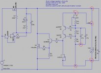
I don't know if the LM317/337 pre-regulator will improve the sound or not but am thinking about giving it a try. The benefits I can think of are:
1. Add some 70dB line regulation before the CCS-shunt. It is not that the line regulation of the CCS-shunt is bad. But maths show us line regulation can further improve, despite being small.
2. Add 1.5A current limit that the LM317/337 provides so that the rectifier diodes won't fail and reduces the inrush currents of some large capacitors used in the raw supply. It may also provide protection to the MOSFETs.
3. Pre-regulating may reduce the heat dissipation of the MOSFETs by a small amount.
4. Possible saving on the capacitance in the raw supply.
5. Other benefits. For example, the transformer may give 27V. The LM317/337 regulates it to 23V, so that my 25V rated capacitors can be used.
Any disadvantages? I can't find any. The LM317/337 may produce its own noise, but I hope the 1R + 470uH choke behind it will get rid of the noise. Increased phase error? Increased impedance? I can't see they are any issues.
The output impedance of anything before the regulator does not matter. Basically that whole stuff that feeds the regulator has one role only: filter. The regulator will present to the load the low output impedance that it can benefit from, better than anything else.
That is good to hear and is what I thought. It is for this reason I thought of using the LM317/337.
I don't know if the LM317/337 pre-regulator will improve the sound or not but am thinking about giving it a try.
It's too easy to find out. You just try it and you'll know the answer. I agree in general with what you listed as potential advantages. The other side of the coin would be more bulk and power consumption, possible oscillation. Nothing major really. I've always said, if I wanted efficiency I wouldn't use a shunt regulator or a 4.6l eight cylinder engine. 🙂
Wouldn't worry about phase error, because it doesn't make much sense to me, really, if you manage to get the noise very low via pre-filtering. Any phase issues would be an intrinsic major problem related to the shunt reg, but that was part of what the design tries to avoid.
Thanks. I see that is a green light for me to go ahead. I will build the thing in the next a few days, first get the fast-soft recovery diodes Salas recommended.
Oscillation with the LM317/337 should not be an issue, unless someone is too keen to put some high Q film cap at the output. I have now the oscillioscope but will first model the circuit in LTSpice. With these tools, it will be fine. I will report back when I get it done.
Cheers,
Bill
Oscillation with the LM317/337 should not be an issue, unless someone is too keen to put some high Q film cap at the output. I have now the oscillioscope but will first model the circuit in LTSpice. With these tools, it will be fine. I will report back when I get it done.
Cheers,
Bill
I'm not saying you shoudn't, but for this kind of thing I find spice less helpful than good old scope and soldering iron. 🙂
Looking forward to more from you, thanks Bill!
Looking forward to more from you, thanks Bill!
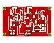
Hi ikoflexer,
do you think the ground-plane version of my layout has HF advantages to the normal version? 🙄
HiFiNutNut replies, that C2 should be placed close to the MOSFET. On my board it is about 30mm away from M1 & M2. I hope this is close enough.
do you think the ground-plane version of my layout has HF advantages to the normal version? 🙄
HiFiNutNut replies, that C2 should be placed close to the MOSFET. On my board it is about 30mm away from M1 & M2. I hope this is close enough.
Attachments

@dvb-projekt
If I see correct, RS+ (remote sense +) is connected to + output trace and RS-(remote sense -) is connected to GND trace?
If I see correct, RS+ (remote sense +) is connected to + output trace and RS-(remote sense -) is connected to GND trace?
@dvb-projekt
If I see correct, RS+ (remote sense +) is connected to + output trace and RS-(remote sense -) is connected to GND trace?
Yes, RS+ close to J2 and RS- close to C1.

I see nothing wrong.
I have read much feedback saying that the location of C2 and it's intrinsic ESR is quite critical to how stable the reg is.
Go back and read the feedback.
I have read much feedback saying that the location of C2 and it's intrinsic ESR is quite critical to how stable the reg is.
Go back and read the feedback.
- Status
- Not open for further replies.
- Home
- Amplifiers
- Power Supplies
- My take on a discrete shunt voltage regulator