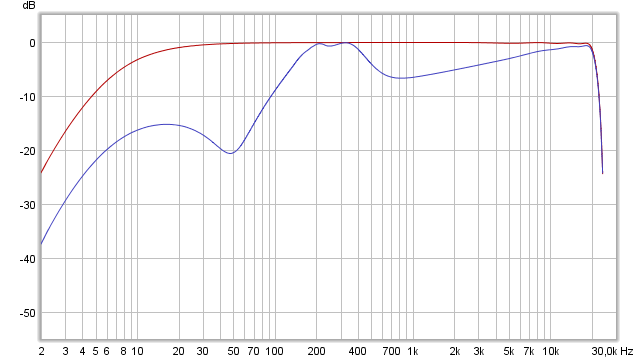
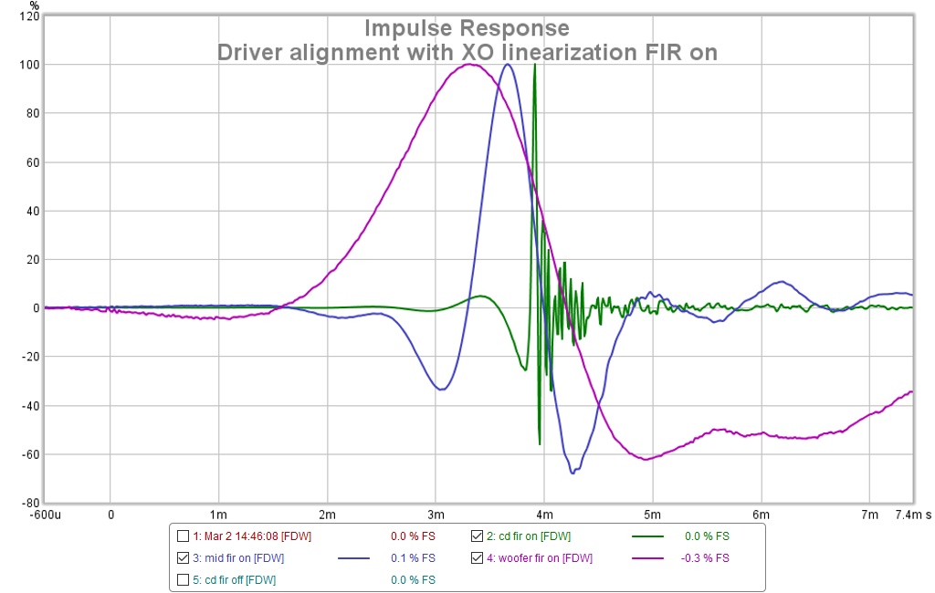
You pretty close with settings for delay and probably just need very small tweak but think its probably impossible to get better when done in pure IIR domain, so suggest write present setting down on a note and then with FIR phase correction turned on start try new numbers and watch the schemes that happen which should give clues what is what down the timeline, as example try sweep with only W/T then M/T then W/M, also as example you can by purpose lower level down 3-6dB for mid which should reveal where it sits in time line into SR. With FIR phase correction turned on and a tonal curve that is falling as frq rise you should get something ala below.
Attachments

Instructive. This reminds me that the IR tells the entire story but also that I don't know how to read it in the IR.
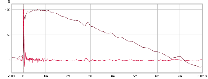
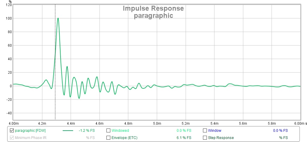
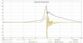
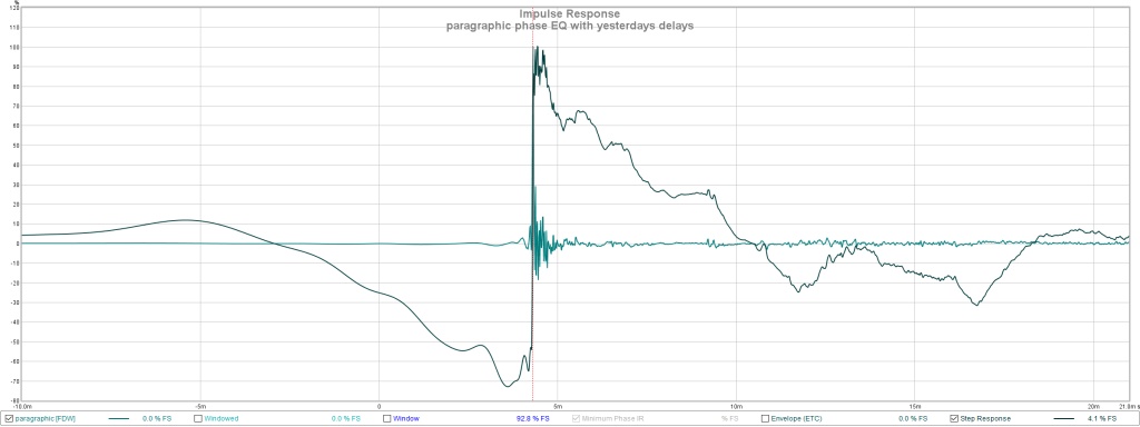
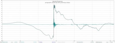
I'll note in passing that the paragraphic phase EQ IR has less ringing, supporting the hypothesis that at least some of the ringing can be EQed away
But if that is ALL ringing, then where are the expected early floor reflections? I did throw some padding on the floor for this measurement but I didn't think it would suppress the floor completely.
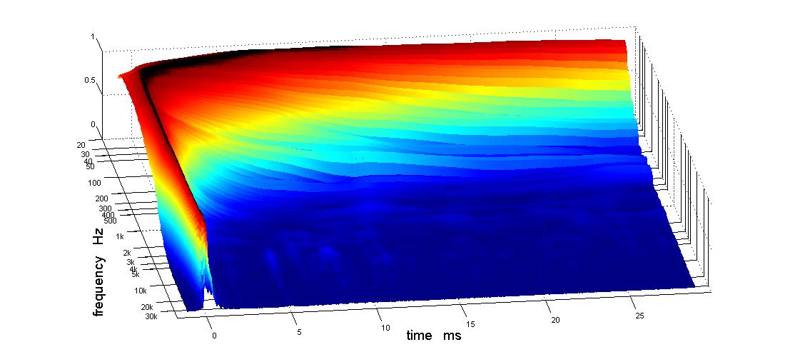
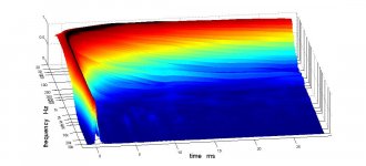
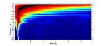
Now I can see what you mean by early waterfall. I set the waterfall time range to 3.6 ms but got a totally different picture viewed from a different angle. you must have different windowing than I was using and different waterfall controls, except the IR windows don't seem to affect the waterfall. Can you tell me the rew settings for reproducing these early waterfalls?

Keep in mind an IR is a chosen rendering of what's happening and you'll see more high frequency peaks than lower ones within that representation.
This is a pretty close measurement, right? The floor reflection will be reduced. Based on the spectrogram plot I'd expect it to be responsible for the wiggles between 200 and 400 Hz. Timing starts at ~5 ms. Look in the filtered IR tab and you'll see the SPL level (down in level because of damping and the close measurement). The effect it has will be reduced because it's down in level compared to the first wave front.
At distances further away it will have a more detrimental effect.
Here's the generated phase plot:
See how it's largely following the FR plot? My goal would be to get the measured phase follow the generated phase as much as possible. Well, with a bit of EQ to clean up the FR 😉.
Yes, the IR tells the whole story, but you can't always tell why the IR looks like it does. If something other than the driver is causing dips and peaks, and we EQ that, it may look very different just a few inches to the left or right.
The more you know what the IR is telling you, the better your results can become. But it's not easy.
If we EQ blindly, the EQ would only be valid at that exact spot. Which is why it's important to know why we have these dips, and if they are at the same spot when we do move the mic just a few inches. What's in common can be EQ-ed out.
Attachments

Last edited:
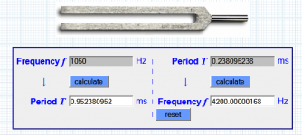
: ) can't stop think 1/4 Period T at 1050Hz is 90º phase lag advanced above 1050Hz if tweeter gets 0,238mS less delay.
Attachments
Last edited:
Had my head down out in the "lab" measuring, missed your posts.
Followed BYRTT's suggestions about looking at SR with one driver missing at a time and got some hints (got impression that mid was late) but there was no strong indication of what to do. Nevertheless I made some delay changes and then trimmed a couple of PEQs in the mid passband and now like what I have. the delay changes improved the mid - woofer xo smoothness
I started out with 1.37 cd delay and 1.85 mid delay. Note delta is close to 1/2 cycle at XO, which is curious. I ended up with 1.57 mid 1.07 cd delay.
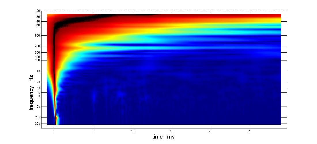
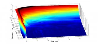
The most pleasing picture is the TDA 3D:
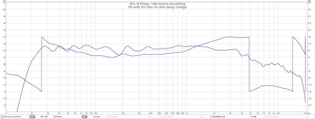
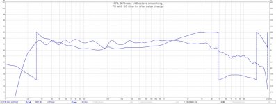
Here is the FR and phase with FIR enabled
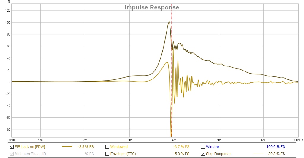
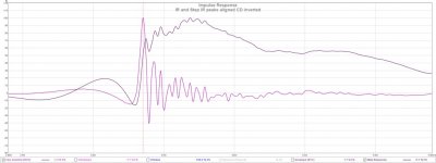
Here is the corresponding step and IR, which now needs to be inverted.
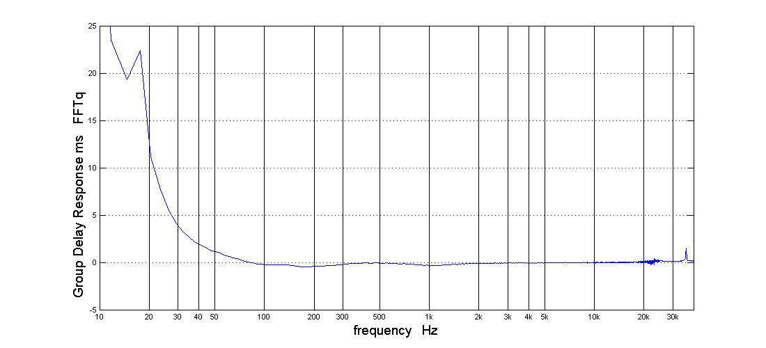
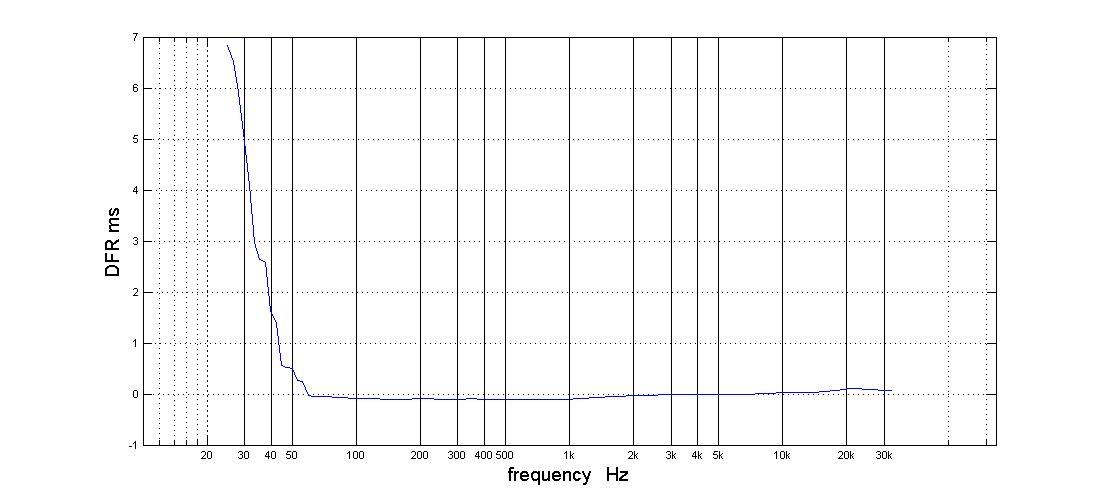
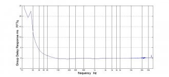
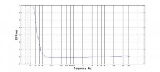
GDR and DFR plots from TDA
Followed BYRTT's suggestions about looking at SR with one driver missing at a time and got some hints (got impression that mid was late) but there was no strong indication of what to do. Nevertheless I made some delay changes and then trimmed a couple of PEQs in the mid passband and now like what I have. the delay changes improved the mid - woofer xo smoothness
I started out with 1.37 cd delay and 1.85 mid delay. Note delta is close to 1/2 cycle at XO, which is curious. I ended up with 1.57 mid 1.07 cd delay.
The most pleasing picture is the TDA 3D:
Here is the FR and phase with FIR enabled
Here is the corresponding step and IR, which now needs to be inverted.
GDR and DFR plots from TDA
Attachments
-
 FR and phase with filter lin after delay change.jpg90.2 KB · Views: 280
 -
 tda3 GDR xo flilter lin and dely change.jpg51.7 KB · Views: 285
 -
 tda3 dfr xo flilter lin and dely change.jpg62.4 KB · Views: 305
 -
 IR and step after delay changes and eq.jpg87.1 KB · Views: 289
 -
 tda pl xo flilter lin and dely change.jpg45.3 KB · Views: 294
 -
 tda3d xo flilter lin and dely change.jpg56.7 KB · Views: 294
Looking for advice/comments on the step response. Everything looks good except for that and while that doesn't look good its the 2nd best so far. I think the best SR was yesterday using paragraphic phase eq instead of xo filter linearization.
Attachments
Looking for advice/comments on the step response. Everything looks good except for that and while that doesn't look good its the 2nd best so far. I think the best SR was yesterday using paragraphic phase eq instead of xo filter linearization...
Good quistions actual my sims also show some 90º phase lag at HF and will try later today run live 3 times bandpass IIR signals thruu DSP and sum them again plus repair with pretended XO filter linearization and report back.
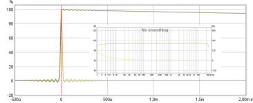
Here is IR wav file sims you had a visual copy to look how IR/SR should line up.
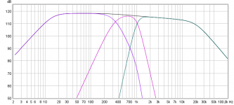
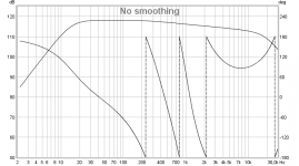
Here is how they sum on "All SPL" tab "T+M+W" and look how phase lag 90º at HF, don't no why but maybe because bandpasses are so narrow and overlapping.
Then in Rephase on "Filters Linearization" tab create pretended known XO points FIR filter LR4/350Hz and LR8/1050Hz.
In REW "All SPL" tab command the two above as "A*B" and now phase doesn't lag anymore at HF and as seen with "Generate minimum phase" its pretty close overlay to absolut phase.
Attachments
the glaring discrepancy between your sims and my measurements are the three phase wraps in your summation vs the two in my measurements. Where does that extra phase wrap come from? Could it be that half cycle of DSP delta delay at/around XO that I have between the CD and mid? Its really easy for me to get the CD mid out of correct phase, just remove that delay and flip CD polarity. The one variation I haven't tried is with that delay removed and CD and mid both inverted. I didn't expect to need such a delay; the CD and mid are only two inches apart on the horn.
the glaring discrepancy between your sims and my measurements are the three phase wraps in your summation vs the two in my measurements. Where does that extra phase wrap come from? Could it be that half cycle of DSP delta delay at/around XO that I have between the CD and mid? Its really easy for me to get the CD mid out of correct phase, just remove that delay and flip CD polarity. The one variation I haven't tried is with that delay removed and CD and mid both inverted. I didn't expect to need such a delay; the CD and mid are only two inches apart on the horn.
Wouldn't the double wrap be because the LR8 crossover has twice as much phase rotation as the LR4?
I don't know but I don't think so. The theoretical model shows three wraps. The measurements show two. Therefore what I'm measuring doesn't match the model. Where do they differ?
Here is a timing model showing electrical filters and delays, both the first and => 2nd sets of delays are in the block diagram. Note that due to the bandpass chamber effect, I only needed a 2nd order electrical filter to hit the 48 db acoustical slope. Perhaps that is the source of the difference.
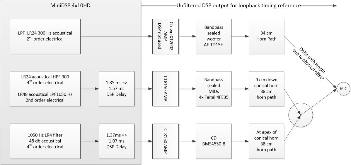
(the circle that arrows from mid and CD both hit symbolizes point source formation)
the woofer amp has DSP which while not being used adds to the woofer latency
Here is a timing model showing electrical filters and delays, both the first and => 2nd sets of delays are in the block diagram. Note that due to the bandpass chamber effect, I only needed a 2nd order electrical filter to hit the 48 db acoustical slope. Perhaps that is the source of the difference.
(the circle that arrows from mid and CD both hit symbolizes point source formation)
the woofer amp has DSP which while not being used adds to the woofer latency
Attachments
How clean are measurement chain (IR) for excess phase from the various coupled I/O and is loop analyzed and reverse corrected into REW, have a laptop that by default enable below filter and while it sound pretty okay on the small build in speaker system it make some distortion into REW 😛.
Attachments
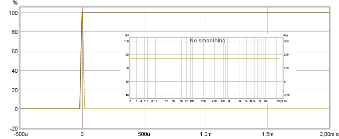
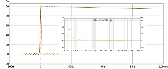
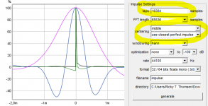
Here's an idea: measure the mids by themselves, without any EQ at all.
Now create an impulse with RePhase, starting with a perfect Dirac pulse and make it look exactly like that mid measurement in slopes etc, the closer the better. Compare the phase on both, is that band pass in a horn behaving like a minimum phase device?
I'd be surprised if it's not.
Now create an impulse with RePhase, starting with a perfect Dirac pulse and make it look exactly like that mid measurement in slopes etc, the closer the better. Compare the phase on both, is that band pass in a horn behaving like a minimum phase device?
I'd be surprised if it's not.
The I/O is very clean - its all digital until DtoA at the output of the MiniDSP. HDMI from the laptop to the AVR and TV and then Toslink to and through the DSPs. The MiniDSP has a balanced output into the amps.
I did some fundamental driver measurements today, not what you are calling for but also relevant.
re' the other part of your post - minimum phase. Is it correct that the theoretical responses that BYRTT creates are minimum phase? Its clear that my XO isn't (even if the driver is) and the generated minimum phase for the response is strange, as we saw last night. Is that a sufficient explanation for why measurements don't match the model?
I measured drivers with filters in place to see how the impulses lined up. I did it both with and without FIR enabled. I was susrprised to find that the results were very different - almost a time reversed impulse overlay.
Apparently, FIR changes time alignment in the process of linearizing the crossover filters. Maybe that is why the paragraphically EQed phase response had by far the best step response, or maybe that was coincidental. I'm not going to speculate; there is more I need to understand.
I tried very hard to get the drivers aligned at the "start" of their impulses. This immediately brings into question what is the start. Is it the first visible sign of the pre-ringing - i.e. where it starts to go down before it starts to rise to its IR peak - or is it that start of the rise towards the peak ? I decided to go with the start of the rise towards the peak.
Then I got caught in a catch 22 bind. As I ramped the mid-cd differential delay to align their starts, I was also changing their relative phase. Whenever I got the starts aligned, I found that I had a reverse phase notch at the crossover frequency. I could solve that by inverting the CD but that didn't help the step response. This bind has something to do with the width of the filtered mids IR peak. Its .57ms from the bottom of the short neg pre-ring of the mid to its IR peak - a lttle more than 1/2 cycle at XO.
My attempts to improve the step response by improving the driver time alignment failed so I went back to last night's result and enjoyed some music.
Attachments
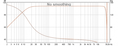
Same exercise as in post 426 but where that was target IR-wav files created in Rephase and manipulated with math in REW "All SPL" tab, this time its live filters set in DSP (JRiver) and REW sweep live for every curve presented here. Technically REW output is set to sweep to JRiver virtual soundcard and listen to input on same souncard as JRiver have as output, so I/O that soundcard is looped back with a cable. Samplerate was set as 48kHz and to save some time had no B&K tonal curve set this time.
Results are into first attachment below and to no surprise show same result as can be done with the 32bit target files imported from Rephase.
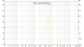
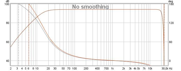
More interesting stuff to look into some reason why predicted FIR filter for XO points gets distorted are old soundcard AP192 from M-Audio has 4 channel I/O where two are SPDIF and other two are analog, so did run test twice, first time via SPDIF then via analog and without any calibration files loaded into REW, below is SPDIF I/O when looped back into REW.
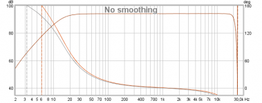
DAC/ADC I/O when looped back into REW.
The three passbands summed via SPDIF I/O and "Generate minimum phase" (grey) overlay close to absolut phase.

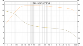
Below is the three passbands summed via DAC/ADC I/O and "Generate minimum phase" (grey) show some deviation from absolut phase caused by excess phase from DAC output and ADC input.
Think above show how just one hardware input and output port ruin precision and theory if not corrected for.
Results are into first attachment below and to no surprise show same result as can be done with the 32bit target files imported from Rephase.
More interesting stuff to look into some reason why predicted FIR filter for XO points gets distorted are old soundcard AP192 from M-Audio has 4 channel I/O where two are SPDIF and other two are analog, so did run test twice, first time via SPDIF then via analog and without any calibration files loaded into REW, below is SPDIF I/O when looped back into REW.
DAC/ADC I/O when looped back into REW.
The three passbands summed via SPDIF I/O and "Generate minimum phase" (grey) overlay close to absolut phase.
Below is the three passbands summed via DAC/ADC I/O and "Generate minimum phase" (grey) show some deviation from absolut phase caused by excess phase from DAC output and ADC input.
Think above show how just one hardware input and output port ruin precision and theory if not corrected for.
Attachments

I did some fundamental driver measurements today, not what you are calling for but also relevant.
re' the other part of your post - minimum phase. Is it correct that the theoretical responses that BYRTT creates are minimum phase? Its clear that my XO isn't (even if the driver is) and the generated minimum phase for the response is strange, as we saw last night. Is that a sufficient explanation for why measurements don't match the model?
I measured drivers with filters in place to see how the impulses lined up. I did it both with and without FIR enabled. I was susrprised to find that the results were very different - almost a time reversed impulse overlay.
Apparently, FIR changes time alignment in the process of linearizing the crossover filters. Maybe that is why the paragraphically EQed phase response had by far the best step response, or maybe that was coincidental. I'm not going to speculate; there is more I need to understand.
I tried very hard to get the drivers aligned at the "start" of their impulses. This immediately brings into question what is the start. Is it the first visible sign of the pre-ringing - i.e. where it starts to go down before it starts to rise to its IR peak - or is it that start of the rise towards the peak ? I decided to go with the start of the rise towards the peak.
Then I got caught in a catch 22 bind. As I ramped the mid-cd differential delay to align their starts, I was also changing their relative phase. Whenever I got the starts aligned, I found that I had a reverse phase notch at the crossover frequency. I could solve that by inverting the CD but that didn't help the step response. This bind has something to do with the width of the filtered mids IR peak. Its .57ms from the bottom of the short neg pre-ring of the mid to its IR peak - a lttle more than 1/2 cycle at XO.
My attempts to improve the step response by improving the driver time alignment failed so I went back to last night's result and enjoyed some music.
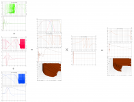
With XO linearization FIR turned on allignment should be at peak but also they should look more symetric balanced when FIR filter correction fit line of IIR domain, so think either FIR filters correction don't fit real line of IIR domain or some other stuff is off, what about numbers of taps into openDRC is those good enough when looking at red curve generated into Rephase verse the blue curves prediction, also wonder if the centering settings in Rephase is spot on for how DSP engine in openDRC works, can say the defaults for centering works for JRiver.
Attachments
Also heard about if samplerate set in Rephase is not same as plug in used into openDRC then correction ends not in line with what planned.
Thanks, BYRTT
Over leisurely morning coffee
If correct lineup with filter linearization is peaks aligned, that is the first thing I will try. That is unambiguous point.
I have verified correct sample rate and sound card flatness
Over leisurely morning coffee
If correct lineup with filter linearization is peaks aligned, that is the first thing I will try. That is unambiguous point.
I have verified correct sample rate and sound card flatness
But given how much timing has to move to align peaks, that will likely not result in smooth FR.Thanks, BYRTT
Over leisurely morning coffee
If correct lineup with filter linearization is peaks aligned, that is the first thing I will try. That is unambiguous point.
I have verified correct sample rate and sound card flatness
Mid peak is about .5 ms past woofer peak
CD peak is about .25ms past mid peak
Exactly!It will if the slopes are ok!
Well what happened is I walked the delays in until the peaks aligned in fear that it would fall apart before I got there. It didn't, but I had a fairly big dip just past the 1050 Hz XO. I started to see if I could EQ it away and a short way into that process, I tried inverting the CD and that cured it. I did some minor re-eq and this is what I have. I see the phase isn't quite right at XO. Step is improved but curious. Questions remain but I think its an improvement.
Have to run now but will return to discuss
Attachments
-
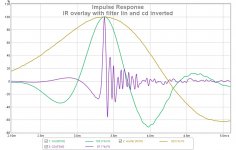 IR overlay with filter lin and cd inverted.jpg122.7 KB · Views: 75
 -
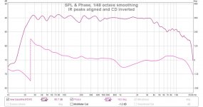 FR and phase with IR peaks aligned and CD inverted.jpg109.4 KB · Views: 75
 -
 TDA 3d IR peaks aligned and CD inverted.jpg57 KB · Views: 76
 -
 TDA pl IR peaks aligned and CD inverted.jpg45.8 KB · Views: 83
 -
 IR and Step IR peaks aligned CD inverted.jpg83.7 KB · Views: 80
- Home
- Loudspeakers
- Multi-Way
- My Synergy Corner Horn and Bass Bins