My last post was wrong. I was looking at step when I thought I was looking at IR. Perhaps that is a less grievous error.
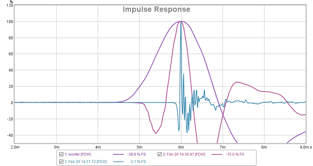
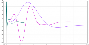
I went through the time alignment process and I think I was successful, given the following overlay of the individual driver IRs:
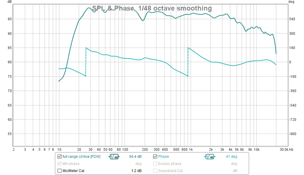
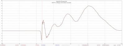
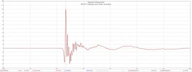
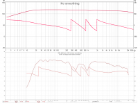
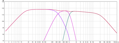
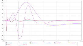
I'm now using 2.97ms dsp delay for the CD and 3.01 ms for the mids. Here is the FR with the same EQ as for the prior rev
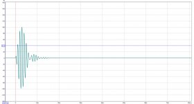
Here is the TDA pl

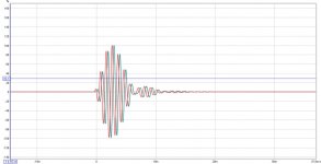
I realize it doesn't match the reference; haven't begun to think about why; step and IR attached
I went through the time alignment process and I think I was successful, given the following overlay of the individual driver IRs:
I'm now using 2.97ms dsp delay for the CD and 3.01 ms for the mids. Here is the FR with the same EQ as for the prior rev
Here is the TDA pl
I realize it doesn't match the reference; haven't begun to think about why; step and IR attached
Attachments
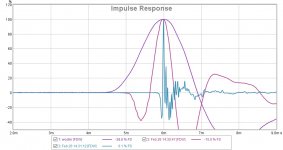
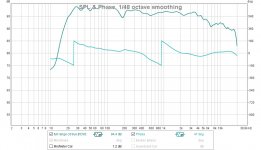
.....I realize it doesn't match the reference; haven't begun to think about why; step and IR attached
IR peak is misalligned on top each other and phase now only turn a total of 360º, also polarity for midrange needs wires or polarity setting in miniDSP flipped to be right.
Below is aproximate IR reference and comparing it looks beside the polarity flip for mids then set your tweeter delay to 1,37mS and mids delay to 1,9mS should bring you pretty close and would like to see TDA pl and REW phase with these settings.
Attachments
EDIT for above : ) think calculated delay for mid is wrong, must be something ala 2,55mS - 2,6mS.
I'm confused. Its definitely true; I'm not just disagreeing politely 🙂
I thought that the definition of time alignment is having impulse peaks aligned in time and the same polarity. Is that not correct?
I thought that the definition of time alignment is having impulse peaks aligned in time and the same polarity. Is that not correct?
I'm confused. Its definitely true; I'm not just disagreeing politely 🙂
I thought that the definition of time alignment is having impulse peaks aligned in time and the same polarity. Is that not correct?
Just read a thread in the REW forum that advised that drivers should be aligned at the start of the rise of the IR. That makes about 1 ms difference for the woofer and about .33 ms for the mid, and almost no difference on the tweeter.
That means I should set the CD delay to 1.42 ms per my measurements which matches BYRTTs' recommendation.
Mid delay should be 1.22 by the same rule. Woofer start is hard to judge ...
Mid delay should be 1.22 by the same rule. Woofer start is hard to judge ...
I'm confused. Its definitely true; I'm not just disagreeing politely 🙂
I thought that the definition of time alignment is having impulse peaks aligned in time and the same polarity. Is that not correct?
Time aligned in this case means making sure the phase lines up, not the peak of the IR. Try BYRTT's suggestion and compare the TDA plot...
I'm confused. Its definitely true; I'm not just disagreeing politely 🙂
Think understand 🙂 but can you please set the suggested delays plus polarity flipped for mids and show system measurement how TDA pl plus REW tab "SPL & Phase" looks.
.....I thought that the definition of time alignment is having impulse peaks aligned in time and the same polarity. Is that not correct?
Regarding IR peaks alligned this holds only true if drivers have exactly same resonse then yes they now alligned, but as soon they are filtered to cover their own unique passband each passband has its role in time domain seen as how wide IR present itself the lower the frq is for passband.
Regarding same polarity can't say exactly why your mid is 180º off but stuff as if filter set in miniDSP get close to 2nd order then electric output change 180º meaning either we have to flip speaker cables polarity or set miniDSP to inverse to correct this behavior. Also some power amps flip polarity 180º at output verse input without any notice in datasheet, so say you have different brand/type power amps for each passband it can happen even you 100% connected speaker cables right that their difference in brand/type create a polarity problem.
Last edited:
can you please set the suggested delays plus polarity flipped for mids and show system measurement how TDA pl plus REW tab "SPL & Phase" looks.
about to do that; took a break to watch a hockey game and then for supper
Regarding IR peaks alligned this holds only true if drivers have exactly same resonse then yes they now alligned, but as soon they are filtered to cover their own unique passband each passband has its role in time domain seen as how wide IR present itself the lower the frq is for passband.
The IR peaks aligned criteria is with filters in place. Nevertheless, lower frequency drivers have slower IR rise times. I can understand how aligning the peaks will not result in a vertical leading edge of the step response, and that aligning the starts of the rises might.
Regarding same polarity can't say exactly why your mid is 180º off
It could be off for any number of reasons; its why you say that it is that puzzles me. Especially since its IR peak has the same polarity as the other drivers.
I will try your suggestions and report back
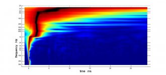
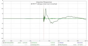
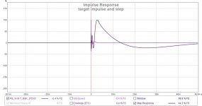
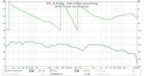
Got some quick data; going back for more; don't think this is what you expected to see.
Attachments
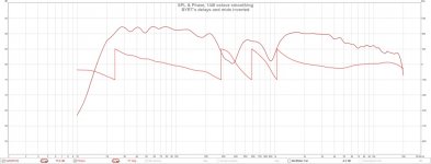
This is what it looks like with BYRTT's delays but the mids NOT inverted. FR, phase and step resemble target (BYRTT's synthetic). TDA shows jump in delay at ~ 1khz.
Attachments
No riple seen in amplitude sum into first plot was not expected but phase is now correct showing phase turn from LR4 plus LR8 XO points, and rest of plots also looks more right now.
Think have to remember my reference plots is exactly system stopbands 15Hz-20kHz with B&K tonal curve and XO points is 350Hz LR4 and 1050Hz LR8 and whereever there is small difference from these data to your actual build settings will make a difference, but overall they start looks same.
Think it looks clear compared there is diffence at system HP where corner horn system roll off more than 2nd order and tweeter start a new roll off scheme about at 3,5kHz, but regarding amplitude riple surrounding midrange slope try more gain for mid band and less gain for tweeter band and maybe very small value correction steps for delay setings trim untill response behave better between respectively mid and woofer plus between mid and tweeter if you know what i mean.
Attachments
Last edited:
I think the corner walls become transparent to the bass around 30 Hz or so and so the corner support falls off.
The tweeter wasn't EQed to the B&K curve. It has a shelf that kicks in around 3.5 Khz.
I was looking at reference curve you posted that had only 2 phase wraps but now realize it was for lower slope XO.
I will try to optimize the FR tomorrow
The tweeter wasn't EQed to the B&K curve. It has a shelf that kicks in around 3.5 Khz.
I was looking at reference curve you posted that had only 2 phase wraps but now realize it was for lower slope XO.
I will try to optimize the FR tomorrow
Time aligned in this case means making sure the phase lines up, not the peak of the IR. Try BYRTT's suggestion and compare the TDA plot...
Isnt there any law and order in the terminology? 🙂
Phase aligned means that the maximum energy is output when 2 drivers are playing the same frequency - i.e. wave peaks are in phase. A system can be phase aligned without being time aligned.
Time aligned means that 2 drivers contribute to create a short pulse with the same relation between duration and peak-level as the input. If a system is time aligned it is also phase aligned - the opposite is not neccesarily true.
No?

//
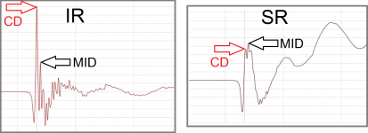
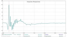
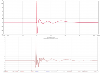
Those delays will be fine tuned. I agree re' the step response. However, look at this CD alone IR. It also has a 2nd peak, could be a horn mouth reflection. Surprising how much the system IR looks like the tweeter IR but I think its normal for the tweeter to dominate the IR.
Attachments
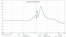
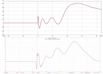
You right CD alone looks have that 2nd peak also that tweeter dominate IR, below is the alligned 3x passbands model that sum to red trace.
I will see if I can duplicate the aligned IR plot tomorrow with measurements.
Now I begin to understand why the mid needs to inverted. Not because the mid needed to be inverted to be "in phase" but because of the number of filters in the mid, its impulse should come out inverted. It goes through an odd number of 2nd order filters. We don't want the IRs of the drivers all pointing in the same direction; we want them pointing in directions consistent with the filter structure.
Last edited:
You right CD alone looks have that 2nd peak also that tweeter dominate IR, below is the alligned 3x passbands model that sum to red trace.
So this I have not been able to get a clear answer on; is time alignment to be done between individual peaks or pulse starts?
//
Isnt there any law and order in the terminology? 🙂
Phase aligned means that the maximum energy is output when 2 drivers are playing the same frequency - i.e. wave peaks are in phase. A system can be phase aligned without being time aligned.
Time aligned means that 2 drivers contribute to create a short pulse with the same relation between duration and peak-level as the input. If a system is time aligned it is also phase aligned - the opposite is not neccesarily true.
No?
//
Yes, quite true I wasn't clear, let me try again... You cannot expect a crossover that introduces time delay to be time aligned in that strict sense. Time aligned is a phrase used to have the speakers you are trying to cross at a certain frequency have their timing line up at that crossover frequency. So to time align these drivers one should only look at the specific timing of the wave shape at that crossover frequency of interest to determine if the drivers are in sync. Not the IR.
Time aligned does not mean time coherency. With these crossover types we are going to introduce delay. Which means you can't determine the time alignment based on the IR alone. One could actually see the alignment if you filter the IR at that crossover frequency for both drivers. Line up the wave shape there. But in REW we can't just filter any frequency of interest. We only have some pré-set values available.
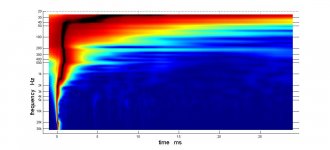
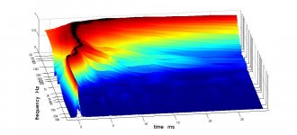
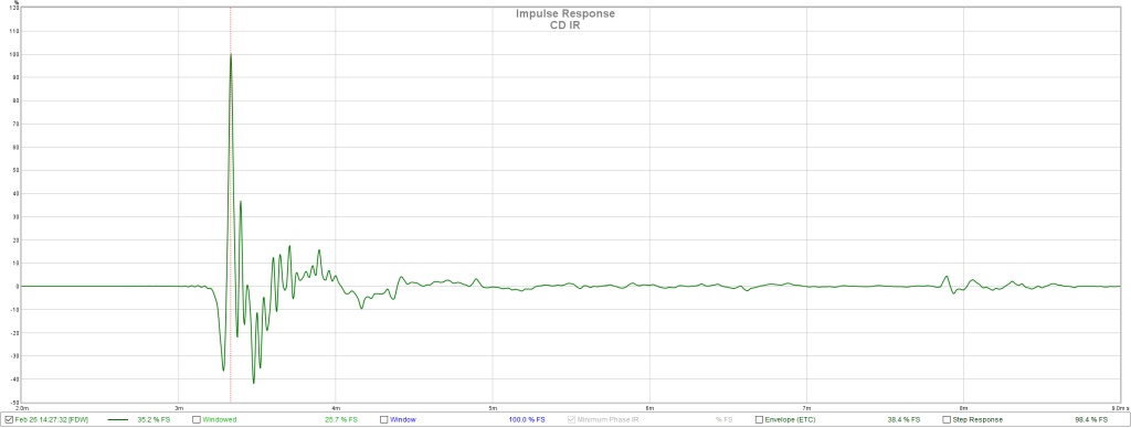
Here's a Dirac pulse filtered at 1000 Hz 1/3 octave:
The filter was set in the Filtered IR tab, after which I stepped back to the %FS view of the IR tab.
If you filter both drivers like this you can see the actual timing match at that frequency of interest.
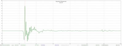
I made an example of that presented with the Overlays function by inserting another Dirac pulse with a slight timing adjustment:
Isn't looking at it this way still time alignment? 🙂 This is the reason for stepped or slanted baffles etc.
Attachments
- Home
- Loudspeakers
- Multi-Way
- My Synergy Corner Horn and Bass Bins