Thanks BRYTT:
I've just spent an hour or two experimenting with exporting filter IRs from refphase to rew for use as target curves, looking at how they sum, and at their GDRs. I think I have that path down pat.
I used your instructions from the rephase thread so thanks for that.
I'm doing that without the B&K curve. I want to keep the IIR XOs simple because the MiniDSP only has 5 peqs per output. I will use separate EQ to apply B&K curve as well as detailed eq through the passband. That way I can play with the voicing without disturbing the XO summation.
Welcome have best fun in process, without really knowing other than REW only present 6x settings when one pick miniDSP in EQ menu sense from other owners around forum that when using https://www.minidsp.com/applications/advanced-tools/advanced-biquad-programming there is much more IIR power than via GUI, there's a spreadsheet at bottom of that link where each tab have some understandable GUI to create various filtering with Advanced Biquad programming.
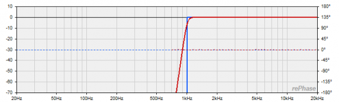
That said to get those slopes created at least visual precise in a hurry sense TDA_EQ is snappy, yesterday started it up for first time with small midwoofer (5FE120) at 1/2 meter on rattling cardboard baffle, without knowing anything just answered ok and in a minute had a correction file to load in APL VST that looks like below. That was the v4 and its defaults startup settings so look forward educate the various possibilities including how to load target curves and then simply push a button.
That said to get those slopes created at least visual precise in a hurry sense TDA_EQ is snappy, yesterday started it up for first time with small midwoofer (5FE120) at 1/2 meter on rattling cardboard baffle, without knowing anything just answered ok and in a minute had a correction file to load in APL VST that looks like below. That was the v4 and its defaults startup settings so look forward educate the various possibilities including how to load target curves and then simply push a button.
Attachments
I've been using miniDSP "adv biquad" programming for a while. Its still not as rich as multiple banks of PEQs in rephase and auto eq doesn't use the biquads.
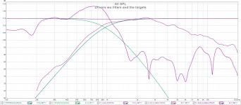
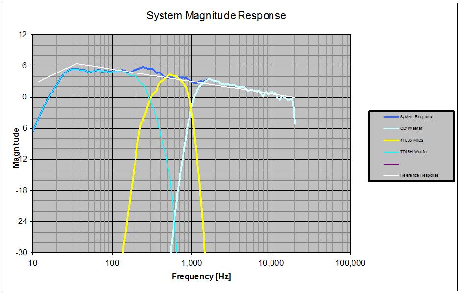
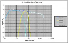
But I have a more serious problem. Look at how my unfiltered drivers with 5 cycle FDW line up against the target curves.
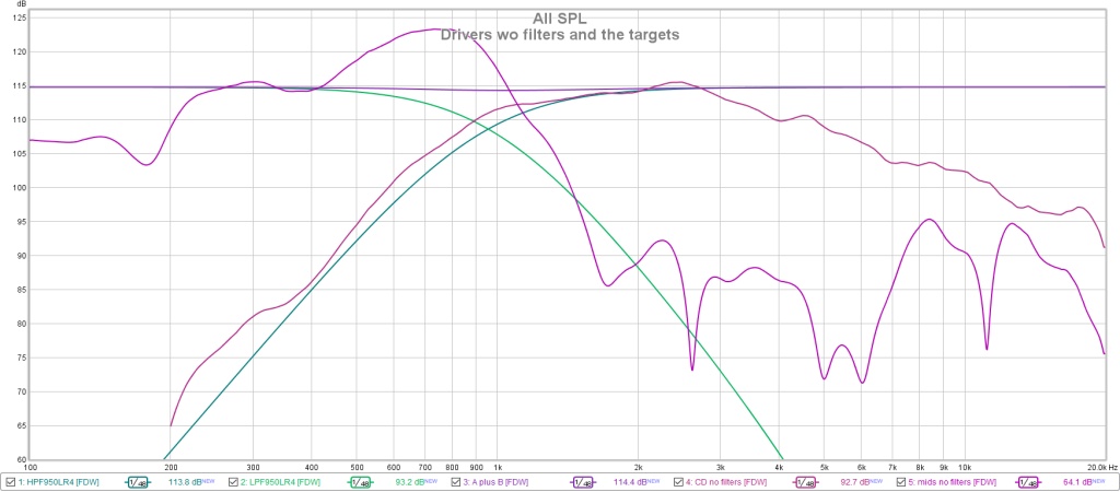
The CD has a natural 24 db/octave slope. The target needs to be at least 12 db/octave steeper. This new measurement is consistent with older ones. I guess my driver responses in the current XO fall below the target curve pretty quickly. I wonder if it wouldn't be better to have a steeper target, probably less strain on the CD.
But I have a more serious problem. Look at how my unfiltered drivers with 5 cycle FDW line up against the target curves.
The CD has a natural 24 db/octave slope. The target needs to be at least 12 db/octave steeper. This new measurement is consistent with older ones. I guess my driver responses in the current XO fall below the target curve pretty quickly. I wonder if it wouldn't be better to have a steeper target, probably less strain on the CD.
Attachments
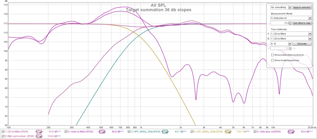
So I only have to do this once more, let me choose the right target curve at the start.
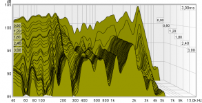
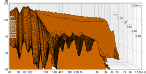
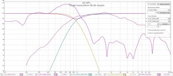
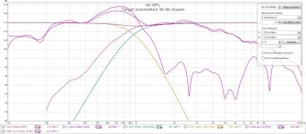
In these pictures, I'm showing the filter curve with the unfiltered driver measurements superimposed plus the rew computed sums of both the filter curves and ther driver curves.
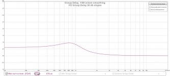
Here is what 36 db slopes look like:
and the 48 db slopes:

and their respective group delay curves:
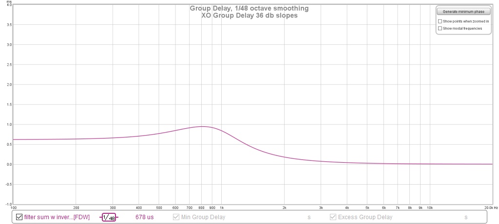
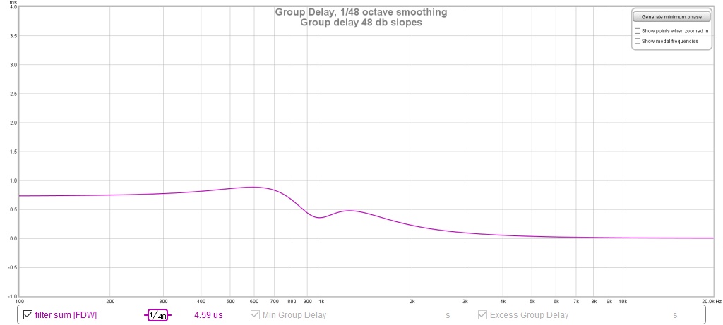
I don't see a compelling reason to choose one over the other. Any opinions?
In these pictures, I'm showing the filter curve with the unfiltered driver measurements superimposed plus the rew computed sums of both the filter curves and ther driver curves.
Here is what 36 db slopes look like:
and the 48 db slopes:
and their respective group delay curves:
I don't see a compelling reason to choose one over the other. Any opinions?
Attachments
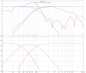
Redoing with 24 db electrical filters for mid CD, which will give me 48 targets
The woofer-mid is going to be 24 db electrical and target. I moved the woofer XO down to 300 Hz for this trial.
I have the XO in ACD but have been unable to get out the measurement equipment to align the drivers and verify it.
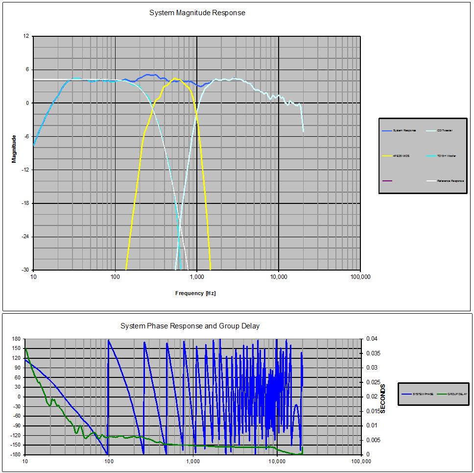
It looks like I'll have considerably more filter group delay in this version. I imported the FRD from ACD into REW hoping to be able to export an IR to TDA but no dice. In fact, REW didn't even show me the phase of the FR.
I ran the system response through FRD Response Blender and extracted min phase response from it:
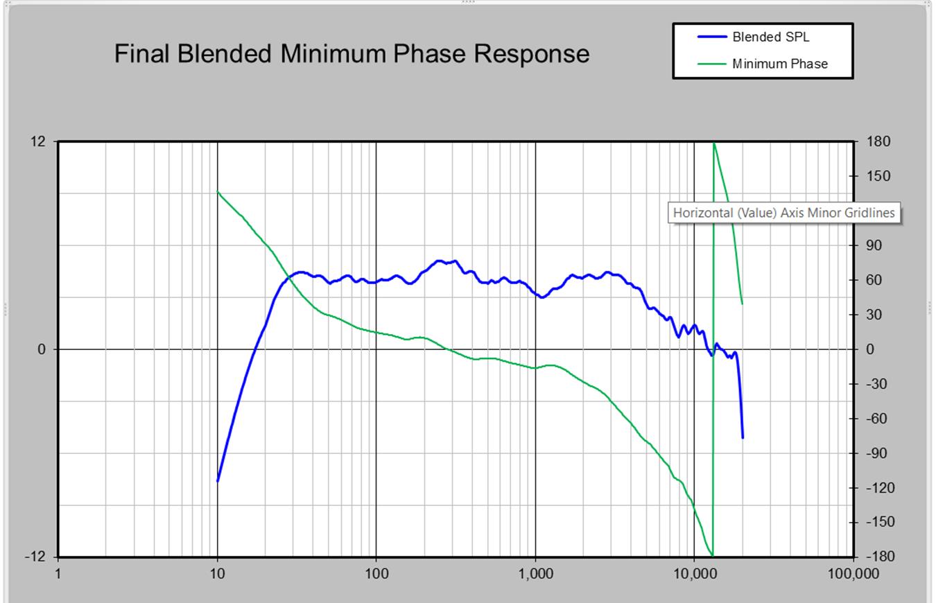
I imported the min phase version of the system response into REW and it still wouldn't show me a phase trace or an IR. I had thought that REW's difficulty was all the excess phase in the response, which comes from the digital delays I am modeling for time alignment. If that were the case, I thought that importing the min phase version would have solved the problem.
@BRYTT: can you tell me how you add the B&K treble rolloff to a target file in RePHase? Thanks!
Jack
The woofer-mid is going to be 24 db electrical and target. I moved the woofer XO down to 300 Hz for this trial.
I have the XO in ACD but have been unable to get out the measurement equipment to align the drivers and verify it.
It looks like I'll have considerably more filter group delay in this version. I imported the FRD from ACD into REW hoping to be able to export an IR to TDA but no dice. In fact, REW didn't even show me the phase of the FR.
I ran the system response through FRD Response Blender and extracted min phase response from it:
I imported the min phase version of the system response into REW and it still wouldn't show me a phase trace or an IR. I had thought that REW's difficulty was all the excess phase in the response, which comes from the digital delays I am modeling for time alignment. If that were the case, I thought that importing the min phase version would have solved the problem.
@BRYTT: can you tell me how you add the B&K treble rolloff to a target file in RePHase? Thanks!
Jack
Attachments

Attach Rephase settings file with IIR B&K curve out to Mhz area, its based on tracing the old pictured/printed curve in B&K pdf document floating around nice internet. Sample rate is set to 384kHz simply change it to same as used by measurement setup. Add a IIR system roll off HP and LP and import to REW outputs sim of speaker system with Linear XO, but to sim speaker with IIR XO points inside system roll offs needs some other and bit more complicated settings, second B&K attachment is for this scenario, and quote own post 273 below to hint how to.
Not that have tried out every feature of REW, but for me looks REW can't show IR without having some wav-file type, one can still make response curves for example at "All SPL" tab say wav-file times frd-file but IR goes dead in the A*B sum because of using frd-file instead of other wav-file. Regarding considerably more filter group delay going higher order can say down the road if wanted can be neutralized with simple L/R channel FIR filter sitting upstream of IIR XO, if that gets a wish think the more precision you get to those acoustic slopes the better the prediction settings in FIR filter will perform.
...Normal target curve IIR pass bands are easy to create on "Minimum-Phase Filters" tab, the one from post 271 having not only system stop-bands but also IIR XO points inside pass-band is bit harder, amplitude system pass-band created on "Linear-Phase Filters" tab and housecurve curve done in PEQ tab, then on "Filters Linearization" tab set stop-bands and XO points, finally make magic on "General" tab invert "Time" and maybe invert "Polarity"....
Not that have tried out every feature of REW, but for me looks REW can't show IR without having some wav-file type, one can still make response curves for example at "All SPL" tab say wav-file times frd-file but IR goes dead in the A*B sum because of using frd-file instead of other wav-file. Regarding considerably more filter group delay going higher order can say down the road if wanted can be neutralized with simple L/R channel FIR filter sitting upstream of IIR XO, if that gets a wish think the more precision you get to those acoustic slopes the better the prediction settings in FIR filter will perform.
Attachments
Thanks!
Oops, need to update RePhase to load the settings.
Wow. that is a mild treble roll off. I know I don't like my treble that hot, despite having old ears. And still like my bass a little hot. Going to have to get my subs into action before too long.
I've been using Raimonds 7dbtarget.txt (modified to limit bass boost below 20 Hz) and imported into ACD as a reference:
Right, I don't need to worry about filter delay so long as I have FIR to correct it. I think the IIR gets me close enough to the desired target that TDA_EQ will have no trouble dialing it in.
As soon as this conspiracy to keep me away from the speakers ends I will finish the work on this XO.
Attachments
Just a thought, I would seriously consider having the drivers follow the LR4 curves, but once they are down more than ~24 dB make the slope steeper. This still gives protection to the driver, and will let them sum as expected.
Last edited:
That is an interesting thought and I've had similar ones, usually in the context of following a shallow slope at first and then getting steep. Here, its the CD that needs protection. Its raw response has a 24 db slope to which I'm adding another 24 db for protection. I think that curve falls more quickly than the excursion requirements rise. I had no problem hitting the resulting 48 db target curve.
Where I have seriously considered such a scheme is to overlap the mids with the woofer to increase the vertical directivity in the region of overlap. I would need to have a steep slope for the mids at no lower than 175 hz and for the woofer no higher than 350 hz. I should take another look at that. I wasn't thinking FIR and RePhase when I gave up on it.
Where I have seriously considered such a scheme is to overlap the mids with the woofer to increase the vertical directivity in the region of overlap. I would need to have a steep slope for the mids at no lower than 175 hz and for the woofer no higher than 350 hz. I should take another look at that. I wasn't thinking FIR and RePhase when I gave up on it.
Wow! Rephase has predefined filters for this "Overlapping 1 or 2 octaves"
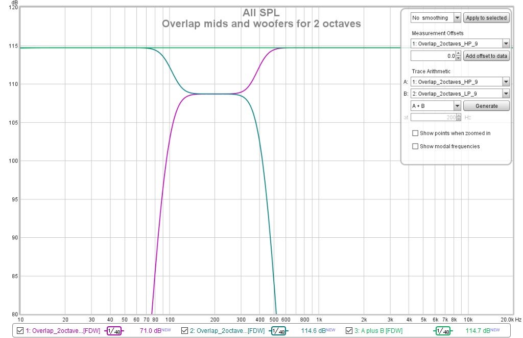
Unfortunately, that is pushing the envelope. The mids excursion peaks at 117 Hz after which output falls off quickly. At 500 Hz, the woofer output will drop towards the edge of the pattern. I really need just 1.5 or 1.75 octaves of overlap. And then I'd need to buy another FIR engine to implement it.
Unfortunately, that is pushing the envelope. The mids excursion peaks at 117 Hz after which output falls off quickly. At 500 Hz, the woofer output will drop towards the edge of the pattern. I really need just 1.5 or 1.75 octaves of overlap. And then I'd need to buy another FIR engine to implement it.
Attachments
The overlap XO is interesting to think about but I don't think it buys me anything with just a single bass bin. I'm already XOing to the woofer at 300 or 350 Hz. Overlap would at best add the horn height to the bass bin slot height to marginally improve vertical pattern control in the frequency range of the bass bin. But the unabsorbed early floor reflections extend up to 1 Khz.
I think it would be more effective for low frequency vertical pattern control to add the 2nd bass bin as originally planned, with overlap, but then the horn would also need a woofer or two to get down below 100 Hz on its own. But I would still end up without vertical pattern control from the upper limit of the bass bins to the vertical pattern control frequency of the Synergy horn.
Probably better off working on floor and ceiling absorption.
If you add 2nd bass on top and measure or calculate top and bottom to be bit different because of position in room then give them each their amp and active steering that let them share response area where they can and where top has trouble boost that area for the lower one and where lower one has trouble boost the missing area for the top, don't know if it works but a thought reminded of from clever unsymmetrical correction wesayso did between his L and R arrays to cover room modes at lows, and that one works.
Haven't gotten close to Wesayso's level of sophistication.
I should do some response measurements at different heights; so far just looked at my seated ear height.
I could lay my head on the floor to get away from that floor bounce🙂
I should do some response measurements at different heights; so far just looked at my seated ear height.
I could lay my head on the floor to get away from that floor bounce🙂
How far apart can the mid holes be?
I'm having some down time in which I'm confined to my desk so I'm doing other things than refining my XO. One of those things was to reread the Synergy patent. In doing so, I found that one of the criteria for forming a point source slightly different than what I remembered:
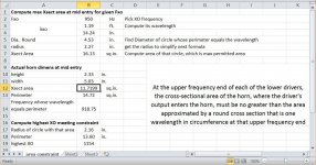
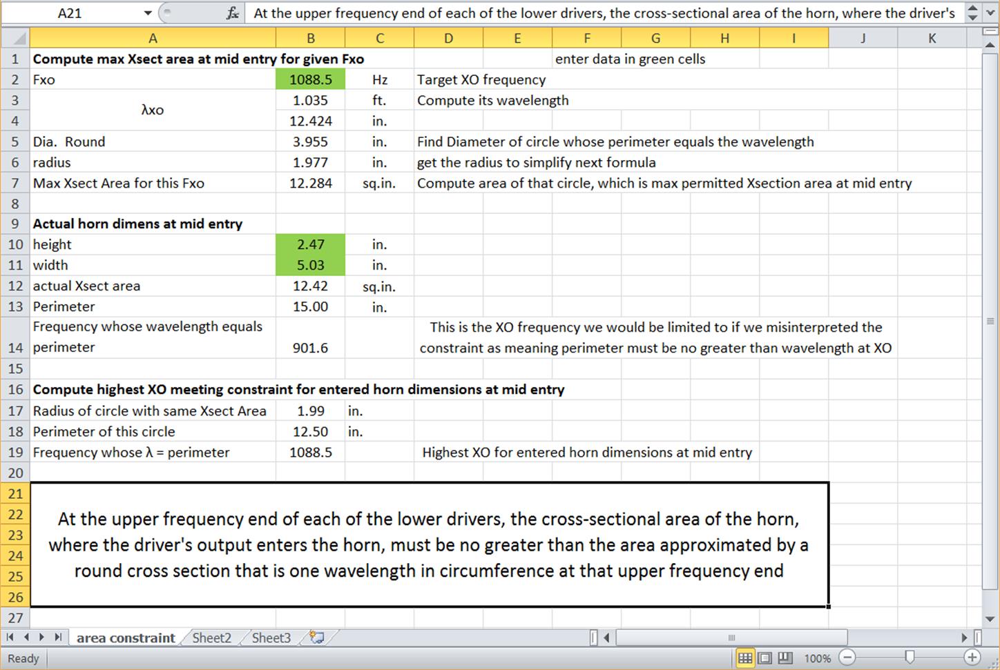
"At the upper frequency end of each of the lower drivers, the cross-sectional area of the horn, where the driver's output enters the horn, must be no greater than the area approximated by a round cross section that is one wavelength in circumference at that upper frequency end"
I (and probably others) approximated this as meaning the perimeter of the horn at mid entry must be less than a wavelength at XO but that isn't exactly what it says. I've also heard others say the mid holes must be less than 1/4 wavelength apart but I couldn't find anything to that effect in the patent.
I made a simple spreadsheet to see if this interpretation makes a significant difference.
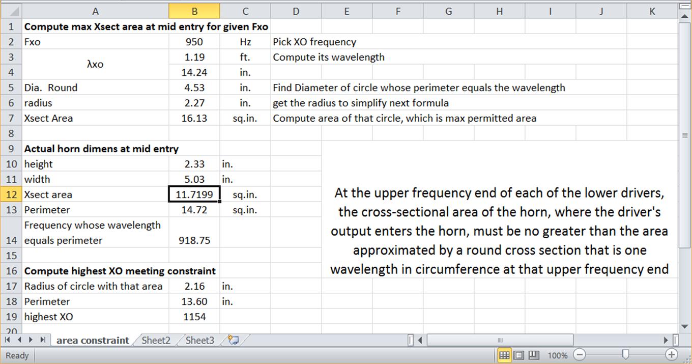
And it does make a difference. By the incorrect interpretation of the rule, I would be limited to a 919 Hz XO. I've been crossing at 950 Hz but I think I grabbed those measurements off an early version of the CAD files. Or more likely I came up with 950Hz on my prototype, then moved the holes out slightly for the 2nd generation. However, the calculation shows I can cross as high as 1154 Hz without violating the rule. This could well ease strain on my CD.
The mid holes on alternate sides of the horn are indeed more than 1/4 wavelength apart, even at 919 hz. I think this could contribute to early roll off of the mids but I don't see how that would inhibit point source formation.
An apparent point source would be the vector sum of contributions from each of the 4 mid holes combined with the output of the CD. By symmetry, the point source must form somewhere on the axis of the horn. By symmetry again, all mid holes are equidistant from any particular point on the axis of the horn. Therefore, the distance between mid holes doesn't affect how the mids' contributions sum into the presumptive point source.
I'm having some down time in which I'm confined to my desk so I'm doing other things than refining my XO. One of those things was to reread the Synergy patent. In doing so, I found that one of the criteria for forming a point source slightly different than what I remembered:
"At the upper frequency end of each of the lower drivers, the cross-sectional area of the horn, where the driver's output enters the horn, must be no greater than the area approximated by a round cross section that is one wavelength in circumference at that upper frequency end"
I (and probably others) approximated this as meaning the perimeter of the horn at mid entry must be less than a wavelength at XO but that isn't exactly what it says. I've also heard others say the mid holes must be less than 1/4 wavelength apart but I couldn't find anything to that effect in the patent.
I made a simple spreadsheet to see if this interpretation makes a significant difference.
And it does make a difference. By the incorrect interpretation of the rule, I would be limited to a 919 Hz XO. I've been crossing at 950 Hz but I think I grabbed those measurements off an early version of the CAD files. Or more likely I came up with 950Hz on my prototype, then moved the holes out slightly for the 2nd generation. However, the calculation shows I can cross as high as 1154 Hz without violating the rule. This could well ease strain on my CD.
The mid holes on alternate sides of the horn are indeed more than 1/4 wavelength apart, even at 919 hz. I think this could contribute to early roll off of the mids but I don't see how that would inhibit point source formation.
An apparent point source would be the vector sum of contributions from each of the 4 mid holes combined with the output of the CD. By symmetry, the point source must form somewhere on the axis of the horn. By symmetry again, all mid holes are equidistant from any particular point on the axis of the horn. Therefore, the distance between mid holes doesn't affect how the mids' contributions sum into the presumptive point source.
Attachments
Good ideas - assume a point source ISN'T formed and then use XDIR to provide the response.
Edge says its pretty close to ideal vertically because the spacing is small and not so good horizontally, where the spacing is 2.5x greater. The spacing is half when you are looking at mid with CD versus the mids by themselves, which makes that picture look better. Of course Edge is pessimistic; it doesn't take the horn into account.
The first order of taking the horn into account is to realize it limits how far off axis one can go. On the 90 Hx 45V horn, one can only go +/- 45 degrees off axis horizontally, where edge shows a 2 db departure from the ideal. Within +/- 20 degrees where I listen, the departure from ideal is insignificant. One can only go +/- 22.5 degrees vertically off axis where the departure from ideal is insignificant.
I think this tells me that at least within my direct listening window, I'm going to get a good response regardless of whether or not a point source forms.
So does a point source really form or do the constraints mean that the mid port holes are close enough to each other and the apex so that it doesn't matter?
Adding the constraint that the mid holes be less than 1/4 wavelength at xo from each other would be to say the latter. The Synergy patent doesn't have this constraint and its clear to me now that it is unnecessary.
There is clear and compelling evidence in the frequency of the cancellation null that a point source composite of, in my case, the 4 mid ports does form on axis of the horn. Think laser confinement. Pressure waves from the mid ports meet on axis and form an epicenter from which sound radiates both forward and backward. The cancellation null frequency is consistent with the backwards wave traveling along the axis of the horn. If the wave traveled along the walls, the path in my 90 degree horn would be 1.414 times longer and the null would be well within the passband. Its not. The measured null is consistent with the mechanical round trip distance from axis point of the mids to the CD diaphragm, less ~1 cm.
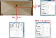
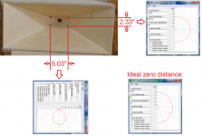
So at least the mids form a point source on axis at the distance of the mid holes. Now delay the CD so at XO its contribution is exactly in phase with the mids and, at least on axis, you perceive a point source. Move off axis to a point in line with the horn wall. In my horn, the distance from the mid's point source to the horn wall is 2.5". Get XDIR out to compute the response assuming independent mid and CD sources. BRYTT did that yesterday for a 2.33" distance. His chart shows that at 45 degress off axis, in line with the horn wall, there is only a small fraction of a dB of difference between sources offset by 2.33" and by 0". This is so close as to not matter. There are other things going on at the fringes of the pattern to completely mask that fraction of a dB, even if it were audible.
Ironically, the answer to my question is both yes and no!
Adding the constraint that the mid holes be less than 1/4 wavelength at xo from each other would be to say the latter. The Synergy patent doesn't have this constraint and its clear to me now that it is unnecessary.
There is clear and compelling evidence in the frequency of the cancellation null that a point source composite of, in my case, the 4 mid ports does form on axis of the horn. Think laser confinement. Pressure waves from the mid ports meet on axis and form an epicenter from which sound radiates both forward and backward. The cancellation null frequency is consistent with the backwards wave traveling along the axis of the horn. If the wave traveled along the walls, the path in my 90 degree horn would be 1.414 times longer and the null would be well within the passband. Its not. The measured null is consistent with the mechanical round trip distance from axis point of the mids to the CD diaphragm, less ~1 cm.
So at least the mids form a point source on axis at the distance of the mid holes. Now delay the CD so at XO its contribution is exactly in phase with the mids and, at least on axis, you perceive a point source. Move off axis to a point in line with the horn wall. In my horn, the distance from the mid's point source to the horn wall is 2.5". Get XDIR out to compute the response assuming independent mid and CD sources. BRYTT did that yesterday for a 2.33" distance. His chart shows that at 45 degress off axis, in line with the horn wall, there is only a small fraction of a dB of difference between sources offset by 2.33" and by 0". This is so close as to not matter. There are other things going on at the fringes of the pattern to completely mask that fraction of a dB, even if it were audible.
Ironically, the answer to my question is both yes and no!
Last edited:
Corrected spreadsheet and max XO calculation
Cleaned up my spreadsheet and corrected my data. Prior horn dimensions were distances between mid holes. Had to add height of mid port slot to vertical distance to get height of horn for use in perimeter calculation.
The resulting max XO is 1089 Hz. The limit due to the misinterpreted constraint is 901 Hz.
spreadsheet is attached
Attachments

Last edited:
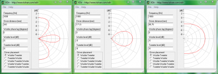
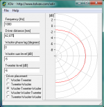
In general many say to unite two drivers be within 1/4 wavelenght and performance is great as a one point source also they sum not only +3dB but +6dB. How this spec looks visual into XDir is in first attachment below for a 1000Hz spaced 1/1 wavelenght then 1/2 wavelenght and finally 1/4 wavelenght, that 1/4 wavelenght is further improved in Synergy when tweeter is in center of 1/4 lenght apart mids down to 1/8 wavelenght as in second attachment.
Below 1000Hz as frq goes Down drivers cooperation lobe will widen but above think we have to remember there is a XO region and inside this region cooperation lobe will narrow as frq goes up. Because Synergy horn is symetrical with tweeter in center could imagine Rephase linear-phase filters "Brickwall" or say 192dB/oct LR would perform good in a Synergy horn and hinder lobe being more and more narrow as frq goes up but its just a thought and will cost some system delay let DSP do the time repair.
Below 1000Hz as frq goes Down drivers cooperation lobe will widen but above think we have to remember there is a XO region and inside this region cooperation lobe will narrow as frq goes up. Because Synergy horn is symetrical with tweeter in center could imagine Rephase linear-phase filters "Brickwall" or say 192dB/oct LR would perform good in a Synergy horn and hinder lobe being more and more narrow as frq goes up but its just a thought and will cost some system delay let DSP do the time repair.
Attachments
Last edited:
- Home
- Loudspeakers
- Multi-Way
- My Synergy Corner Horn and Bass Bins