re' 6 db
right there is a 3db efficiency increase when drivers are within 1/4 wavelength. I don't recall why this is true but I do recall it. Its built into HornResp for arraying
your first figure shows the (dreaded) lobing due to excessive driver separation. Interesting at 1/2 wavelength, there is no lobing but a narrower beam than at 1/4 wavelength separation. I think existence of a lobe would argue (very strongly 🙂) against the possibility of formation of a point source but I don't think absence of a lobe is a sufficient condition for one to form.
I agree that 1/4 wavelength separation is better than 1/2 wavelength separation but I don't see that as addressing whether or not <= 1/4 wavelength separation is necessary for a point source to form. I still find my argument involving the reflection null frequency compelling.
re' brickwall
The original point of Synergy was to be able to get linear phase with passive or IIR XO.
All very interesting, surprising what you can come up with when you only have a computer to play with.
Can you raise your crossover point in practice though? Doesn't the cancellation from the extra path length in the BMS limit your mid range output up high? This was what I always found in simulation that the BMS had to be crossed lower to match up with the mids.
I think what you get in practice is probably more important than what any perceived rules say. Many of the more recent synergy inspired deigns have gone further from the original and have shown good measurements.
From memory the 6dB comes from the 3dB in acoustic power from 1/4 wavelength summing and the 3dB from electric power of having two sources.
...
The original point of Synergy was to be able to get linear phase with passive or IIR XO.
That was just one of the points. According to Tom, it was to use one horn over a large bandwidth and have it radiate as a point source. The 'linear phase' with passive crossover is hard to do with a wide angle coverage horn, because the midrange doesn't get much of a headstart over the tweeter. If phobias about DSP being EVIL aren't an issue, a FIR phase EQ is a great modern way to get to linear phase once point source radiation is achieved. I've done that, but really haven't been able to see that the sound is any better when linear-phase. Better on a scope and better per intellect, but not a big effect in listening.
I can indeed raise my XO. The cancellation notch is somewhere around 1400 Hz.All very interesting, surprising what you can come up with when you only have a computer to play with.
Can you raise your crossover point in practice though? Doesn't the cancellation from the extra path length in the BMS limit your mid range output up high? This was what I always found in simulation that the BMS had to be crossed lower to match up with the mids.
I think what you get in practice is probably more important than what any perceived rules say. Many of the more recent synergy inspired deigns have gone further from the original and have shown good measurements.
From memory the 6dB comes from the 3dB in acoustic power from 1/4 wavelength summing and the 3dB from electric power of having two sources.
In my relatively wide 90H horn, the mid hole locations were dictated by the cross sectional area rule and so the cancellation notch is up higher than it would otherwise be.
That was just one of the points. According to Tom, it was to use one horn over a large bandwidth and have it radiate as a point source. The 'linear phase' with passive crossover is hard to do with a wide angle coverage horn, because the midrange doesn't get much of a headstart over the tweeter. If phobias about DSP being EVIL aren't an issue, a FIR phase EQ is a great modern way to get to linear phase once point source radiation is achieved. I've done that, but really haven't been able to see that the sound is any better when linear-phase. Better on a scope and better per intellect, but not a big effect in listening.
My comment about the main point of Synergy was intended ironically to counter the suggestion to use brickwall filters. Definitely, point source is the more important part of the invention.
I've gotten just about to linear phase with DSP and only IIR filters. All I did was equalize to hit target acoustic LRx target curves and then adjust DSP delays to align driver impulse response peaks with those filters in place. Using FIR to make the phase response textbook flat is pretty far down on my to do list but it may fall out of the room equalization process.
I can indeed raise my XO. The cancellation notch is somewhere around 1400 Hz.
In my relatively wide 90H horn, the mid hole locations were dictated by the cross sectional area rule and so the cancellation notch is up higher than it would otherwise be.
As long as the output from the mid doesn't roll off too early you should be good. I can't remember off hand what your un EQ'd mid response looks like. All my sims looked like 950Hz was the best choice no matter where I put the mids.
Did you make it lower for a better/easier match or because you thought it was violating a rule to have it higher? 😕
My comment about the main point of Synergy was intended ironically to counter the suggestion to use brickwall filters. Definitely, point source is the more important part of the invention.
I've gotten just about to linear phase with DSP and only IIR filters. All I did was equalize to hit target acoustic LRx target curves and then adjust DSP delays to align driver impulse response peaks with those filters in place. Using FIR to make the phase response textbook flat is pretty far down on my to do list but it may fall out of the room equalization process.
Yes lets forget those brickwall filters it was only thoughts and have to be tested if works well beside in being FIR DSP will cost some overall system delay.
About you got just about linear phase with IIR filters think that actual implementation had some errors and not only me that thought so, it was also pointed out by wesayso and Raimonds. Heart of that problem was probably trying to force (time step) standard textbook LR4 slopes to sum flat group delay doesn't work very good probably because actual group delay per bandpass change numbers inside its passband and Tom Danley also shared many times he doesn't use standard texbook XO filters. Over my head how Tom Danley XO but have seen in sims other slopes where change numbers in group delay happens outside passband and think something ala that scheme could be much better forced to sum with a suddenly time step. Suggest don't subjective use the previous wrong flat phase configured setup to judge how a correct linear phase XO will sound in long run.
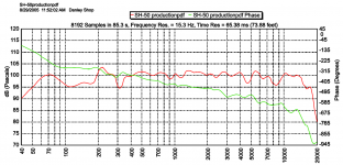
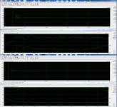
Seen many mention SH-50 as linear phase but think its rather kind of relative flat nice strait line, in datasheet note phase scale is covering 900º, second attachment is Tom Danley share a Rephase exercise linearization for SH-50 at this link http://www.diyaudio.com/forums/multi-way/244508-monster-massive-23.html.
Attachments
Last edited:
Yes lets forget those brickwall filters it was only thoughts and have to be tested if works well beside in being FIR DSP will cost some overall system delay.
About you got just about linear phase with IIR filters think that actual implementation had some errors and not only me that thought so, it was also pointed out by wesayso and Raimonds. Heart of that problem was probably trying to force (time step) standard textbook LR4 slopes to sum flat group delay doesn't work very good probably because actual group delay per bandpass change numbers inside its passband and Tom Danley also shared many times he doesn't use standard texbook XO filters. Over my head how Tom Danley XO but have seen in sims other slopes where change numbers in group delay happens outside passband and think something ala that scheme could be much better forced to sum with a suddenly time step. Suggest don't subjective use the previous wrong flat phase configured setup to judge how a correct linear phase XO will sound in long run.
Seen many mention SH-50 as linear phase but think its rather kind of relative flat nice strait line, in datasheet note phase scale is covering 900º, second attachment is Tom Danley share a Rephase exercise linearization for SH-50 at this link http://www.diyaudio.com/forums/multi-way/244508-monster-massive-23.html.
You are right of course in your middle paragraph but that was too long a story to get into for a quick reply -I did have it in mind while replying but didn't include it in the reply. I'm about ready to test a new XO which hopefully won't have implementation errors in it. It has 48 db acoustic slopes and Fxo= 1050 Hz.
Regardless of whether I had implementation errors though, I didn't have to force a flat summation. I simply EQed to the target LR4 curve, which just required a couple of PEQs, and a flat summation happened. This made me a believer in EQing the driver to the target roll off curve instead of EQing it flat and then applying the target filter. Mathematically, this should work unless phase doesn't track through the XO region.
I think the reason TD doesn't use standard textbook XO slopes is because he also doesn't use DSP delay for time alignment. He has to achieve the necessary delay some other way - via mid port location and non-standard slopes and overlaps, which, if one can do it, requires fewer components than would a separate all pass filter.
What is this sudden time step you mentioned? If drivers are time aligned via DSP delay, there shouldn't be a time step when crossing from one to the other. If I have the CD and mids out of phase with each other than I would have a ~.5 ms time step. Curiously, that is what I see in TDA's DFR but not in the min phase subtracted GDR, which Raimonds says is the XO GDR
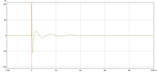
Here is a DFR that shows the time step. This pre-EQ DFR from a TDA_EQ measurement. TDA shows similar thing but couldn't find one easily.
So I will be alert to possibility of CD inversion. What is the best way to verify driver polarity? I've been making sure the impulse response peaks are the same polarity.
Attachments
As long as the output from the mid doesn't roll off too early you should be good. I can't remember off hand what your un EQ'd mid response looks like. All my sims looked like 950Hz was the best choice no matter where I put the mids.
Did you make it lower for a better/easier match or because you thought it was violating a rule to have it higher? 😕
I think all the thinking one does about the XO when still in the simulation stage goes out the window when facing real measurements - similar to battle plans.
I started out with 950 Hz because I mistakenly thought that was as a round off of as high as the rule permitted.
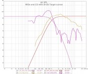
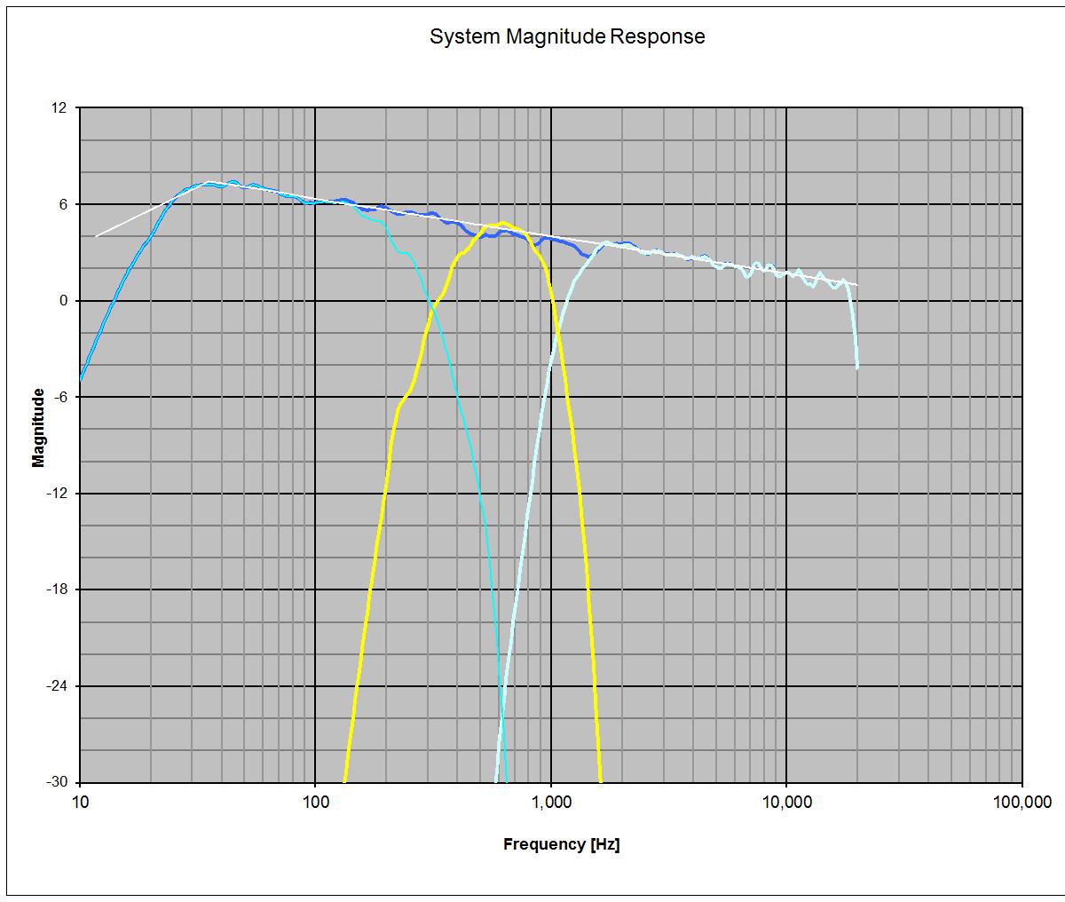
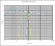
Let's take look at my latest measurements plotted against 24 db slope target curves. You see that I'm flattening the horn gain and bandpass peak of the mids so that they extend down to 200 Hz or so and that the unfiltered mid curve is above the XO target curve through the XO region. I've offset the curves so that the unfiltered mids and CD response cross at 1050 Hz, my new target XO.
Attachments
Here is the predicted response from ACD, the XO program that I'm about to test. I applied a house curve as a final reference curve in ACD and EQed to that outside the crossover regions. The house curve is Raimond's 7db.txt modified to stop calling for boost below 30 Hz because I saw distortion rising there in my woofer.
Attachments
.....What is this sudden time step you mentioned? If drivers are time aligned via DSP delay, there shouldn't be a time step when crossing from one to the other. If I have the CD and mids out of phase with each other than I would have a ~.5 ms time step. Curiously, that is what I see in TDA's DFR but not in the min phase subtracted GDR, which Raimonds says is the XO GDR.....
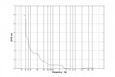
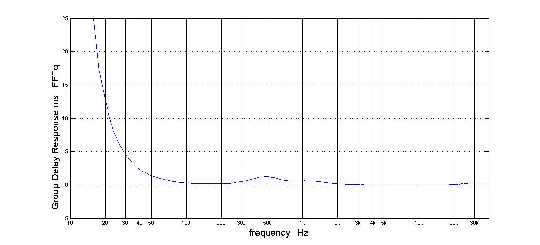
The suddenly time step is when taking the relative flat part from woofer and mid and force those two the about 2mS forward in time relative to tweeter when looking at how group delay the three band-passes are supposed to perform for LR 4th order slopes.
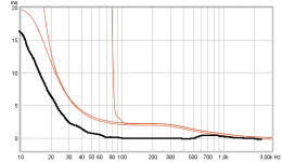
As example this plot show group delay the three band-passes each by each now take the one belonging to woofer and mid and time step forward relative to tweeter as the black handmade trace model, this gives nice flat phase and flat group delay althoug a tiny bumb in transition area. Doing this step in electric domain will cause error in amplitude sum for that specific LR slopes but in acoustic doamain probably more forgiving because of wide dispersion plus live room environment and other measurement design axis than strait in center.
Attachments
The suddenly time step is when taking the relative flat part from woofer and mid and force those two the about 2mS forward in time relative to tweeter when looking at how group delay the three band-passes are supposed to perform for LR 4th order slopes.
As example this plot show group delay the three band-passes each by each now take the one belonging to woofer and mid and time step forward relative to tweeter as the black handmade trace model, this gives nice flat phase and flat group delay althoug a tiny bumb in transition area. Doing this step in electric domain will cause error in amplitude sum for that specific LR slopes but in acoustic doamain probably more forgiving because of wide dispersion plus live room environment and other measurement design axis than strait in center.
I don't quite follow but I do recognize that so-called hand made trace. It looks like what TDA shows me as the 950 Hz 24 db acoustic XO GDR.
In this measurement, I was delaying the mids by 2.06 ms and the CD by 2.35 ms to align them with the woofer, which has about 2ms of horn path delay itself at its XO to the mids. In addition, I believe the CD is .17 ms behind the mids because of mid entry position on the horn.
Attachments
Basicly with a known target scheme especially when measured in trusted nearfield acoustics should show same curve as syntetics or electric domain target curves would perform and say you at that time had the precise slopes at place then acoustic offset between drivers were off and stepped in time because else it had looked close to the syntetic texbook one, but in general think because that XO scheme was dropped after Raimonds gave advice and belong to past think no reason to walk over it again, lets look forward the new XO scheme and what it brings 🙂.
I think all the thinking one does about the XO when still in the simulation stage goes out the window when facing real measurements - similar to battle plans.
Very true. You mentioned up to 1400Hz before which is what confused me. I thought 1K or there about which is what you have chosen. The 48dB slope will probably make target matching easier too as the mid rolls off pretty fast past 1K.
I doubt Tom gets the Synergy rule book out to check if his latest design fits. Anything that has been patented will need to have been described in detail to get it over the line but there will always be some wiggle room and as you say above measured reality is what you need to work from.I started out with 950 Hz because I mistakenly thought that was as a round off of as high as the rule permitted.
I look forward to see if you think your new crossover has any audible improvement when it is done 🙂
new XO
This XO has 48 db acoustic slopes on the mid/CD at 1050 Hz. I think the steeper slopes and higher XO frequency have helped the sound. I think I can do better on the woofer XO. It was a real struggle to stay close to the 24 db target slope and the ripple in the transition region shows it. The woofer really wanted to fall off faster. I should have let it do so.
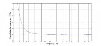
The group delay isn't much different than what we've seen before. The direct response line in TDA still bends but more gently than before:
this is the group delay with min phase subtracted and thus the XO group delay:
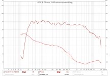
I swept the dsp delays through ranges around their final settings to be sure I had at least a local optimum. Here is the FR and phase that resulted.
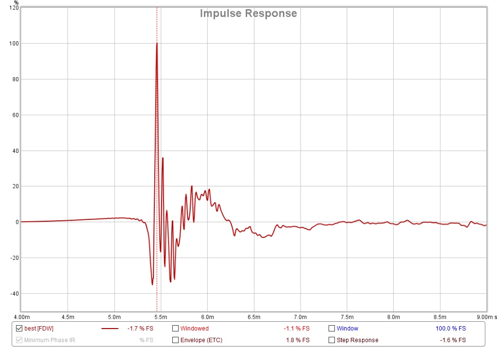
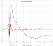
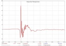
and the IR
I'm out of EQ resources for improving the above in the miniDSP 4x10 but have both APL1 and OpenDRC FIR engines for a next step.
This XO has 48 db acoustic slopes on the mid/CD at 1050 Hz. I think the steeper slopes and higher XO frequency have helped the sound. I think I can do better on the woofer XO. It was a real struggle to stay close to the 24 db target slope and the ripple in the transition region shows it. The woofer really wanted to fall off faster. I should have let it do so.
The group delay isn't much different than what we've seen before. The direct response line in TDA still bends but more gently than before:
this is the group delay with min phase subtracted and thus the XO group delay:
I swept the dsp delays through ranges around their final settings to be sure I had at least a local optimum. Here is the FR and phase that resulted.
and the IR
I'm out of EQ resources for improving the above in the miniDSP 4x10 but have both APL1 and OpenDRC FIR engines for a next step.
Attachments

.....I'm out of EQ resources for improving the above in the miniDSP 4x10 but have both APL1 and OpenDRC FIR engines for a next step.
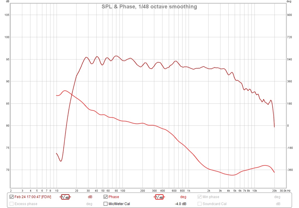
Think APL1 can help with even more pro IIR correction and OpenDRC can linearize XO points, but before that next step take a look at phase which is supposed to turn 1080º by XO points alone plus 180º at each end of system stop-bands. So miss about 540º phase turn in your REW curve which indicate somewhere time step between pass-bands and/or also mismatched polarity can play a 180º wrong step role. Looking attack side of IR woofer fire too early indicated by step starts going more than numbers of 30 in negative direction, where negative direction should only happen at decay side of IR.
Think goal must be in miniDSP to get those acoustic centers perfect alligned and also rechecked for any polarity mismacth, then FIR correct the known XO point in OpenDRC and finally use APL1 to finetune anything left including a good tonal response.
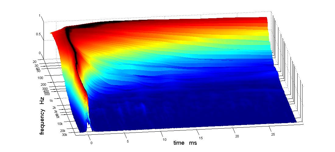
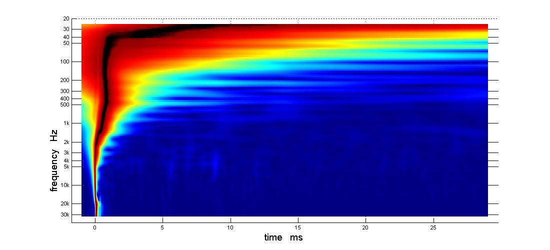
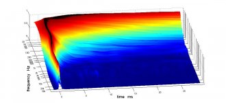
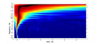
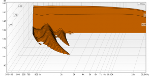
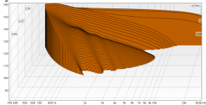
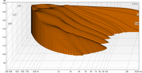
Models below use 15Hz and 20kHz as system stopbands and 350Hz LR4 plus 1050Hz LR8 as XO points with a B&K tonal curve. First is ordinary IIR XO points which give some delay that add some long tails high up in frq when viewed into waterfall plots, second is when 1050Hz point is FIR linearized and third have also 350Hz point linearized.
Attachments
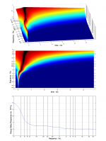
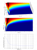
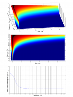
Points in previous post is don't add FIR before IIR system is alligned perfect and predict as such a IIR domain is supposed to perform, then adding the known IIR XO points some FIR correction will do the wonders and clean up waterfalls so that mids will perform beatifull decay, below is waterfall for the three models.
Attachments
Very interesting plots, BYRTT.
I was suspicious of the timing also. I hoped you would chime in.
Looking through my measurements, I see REW was marking time at the midpoints of the first rise of the IR instead of the peak. Shame on me for not checking sooner. Mid and CD off by <.2 ms but woofer off by .89 ms. That might explain the woofer firing early but not the missing 540 degrees but it is a start.
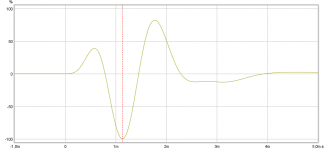
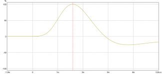
Come to think about regarding having correct same polarity the three pass-bands is maybe bit difficult to check because no diagraph is visible and if actual filter in miniDSP end up as 2nd order it will electric reverse cone direction. So before any calibration for offset timing to ensure polarity is absolut correct suggest run system with speaker cable only connected for one band at a time using below IR figures as reference and then adjust if they happen be out of sync.
Attachments
Last edited:
- Home
- Loudspeakers
- Multi-Way
- My Synergy Corner Horn and Bass Bins