I did some major tweaking today on my projector, and was able to achieve good results!
I was using an old (not working) SGI panel that I had masked off to be the size of a 15.4" panel.
The Results:
I could see the screen door corner to corner, but in order to see the screen door in the corners I needed to get real close because they were pretty dark, I probably need to adjust my bulb *sigh*
Anyways, the middle of the screen had the super crisp screen door where you could make out the red/green/blue parts of the pixels...then onto the edges where I could see the screen door pretty good still, then when you got up to the corners all you could make out were the squares.
Its not perfect, but it should work fine for WUXGA, let alone XGA. when I get my WUXGA kit and pop it in there im going to do some serious pixel searching.
For now, I will continue to tweak.
thanks hezz for your information.
the brainchild setup is closer than what i say than what GG's setup. Mean he is focusing at full lens area, (focusing beyond so the light cone fitts perfectly)
I know in perfect world this is the perfect setup, but i believe in real world it would be something between this and GG's, since lamp is not small and there are no perfect fresnells. but i believe this is a good stating point. So can we check what field fresnell focal would be better for 3dlens? if you agree, if not lets go on discussing.
do you know the deffinition of FOV hezz? (i don´t)
I don't know a difinition for FOV and after having designed a lens a I'm inclined to think that there are two concepts for FOV.
The first is the corrected field of view. This is the angle for which the lens has been corrected. In other words, within the corrected FOV the lens will have resolution ability to a target resolution out to that range.
With all lenses the center axis of the lens will always be brighter and better focused because there is less chromatic and spherical abberations.
The correction for imaging objects is done to a target resolution called a spot size. With a high quality lens the spot size is very small out to the edge of the claimed FOV. What this means is that differing wavelengths of light will focus in nearly the same exact spot and be closer to the shape of the original image spot.
Now there is the absolute FOV which is the angle that the lens can recover and focus an image that is to some degree recognizable. With relaxed image correction the spot size or the amount that the lens system distorts the original image and focuses different wavelengths at less accuracy is increased.
This is what is causing the less precise imaging at the edges that Minoten is observing. All lenses have it. It's just a matter of how much distortion there is. The higher correction there is out to a wide FOV the more expensive and harder to manufacture the lens. Super high resolution lenses typically have eight or nine elements because it is necessary for very high end correction.
The typical high end modern fixed FL photographic lens has about eight or nine elements because it is corrected to an even higer degree. The wider the FOV is at high image correction the more elements the lens needs also.
Hezz
8 or 9 element lenses
I have a 600 mm fl Rodenstock APO-Ronar lithography production lens that only contains four elements. I get razor-sharp screendoor from corner to corner with this lens. I can also see the individual R, G, and B stripes within every single pixel on the screen.
Beyond a certain quality lens, LCD projection just can't get any better. I think the main limitation is the pixel size on the screen. Even if your spot size is 1/4 the pixel size, you will get a very sharp image. And that is not a very small spot size at all!
There are a lot of lenses out there that were designed for extremely precise film applications, like my process lens. But they are way over-engineered for LCD projection. What we really need are cheap triplets with a maximum field angle wide enough for our LCDs, that are just good enough for 1080p HD LCD's pixel size.
I tried designing a non-optimised triplet using off-the shelf eyeglass lenses to see if this is possible. (I used acrylic for the positives and glass for the negative lens to get the different dispersion characteristics.) Looks pretty good (tiny spot size) in the OSLO modelling program, but in real life the uncoated optics wipe out the image. If I added the cost of coatings, it would be more than the 450 mm fl triplet sold at DIY projector forum stores!
Hezz and/or Minoten,
Do you think the 330's and 135mm triplet are going to give you a good image after all? Have you gotten any improvement on corner brightness and focus?
What are your current distances, including fresnel <-> LCD?
My optics still have not shipped from DIYPC! 😡 18 days without replies to my emails requesting information. 😡 >35 days since I placed my order. I would have already canceled my order, but I have yet to source the parts from elsewhere.
I now have to strongly recomend not doing buisness with DIY Projector Company.
Re: 8 or 9 element lenses
very interested in your eyeglass-made-triplet design. can you post it. Maybe in another seperate thread.
I can get coated glass eyeglasses (uncut) very cheap from China. I will check the price for acrylic lenses.
very interested in your eyeglass-made-triplet design. can you post it. Maybe in another seperate thread.
I can get coated glass eyeglasses (uncut) very cheap from China. I will check the price for acrylic lenses.
Guy Grotke said:I have a 600 mm fl Rodenstock APO-Ronar lithography production lens that only contains four elements. I get razor-sharp screendoor from corner to corner with this lens. I can also see the individual R, G, and B stripes within every single pixel on the screen.
Beyond a certain quality lens, LCD projection just can't get any better. I think the main limitation is the pixel size on the screen. Even if your spot size is 1/4 the pixel size, you will get a very sharp image. And that is not a very small spot size at all!
There are a lot of lenses out there that were designed for extremely precise film applications, like my process lens. But they are way over-engineered for LCD projection. What we really need are cheap triplets with a maximum field angle wide enough for our LCDs, that are just good enough for 1080p HD LCD's pixel size.
I tried designing a non-optimised triplet using off-the shelf eyeglass lenses to see if this is possible. (I used acrylic for the positives and glass for the negative lens to get the different dispersion characteristics.) Looks pretty good (tiny spot size) in the OSLO modelling program, but in real life the uncoated optics wipe out the image. If I added the cost of coatings, it would be more than the 450 mm fl triplet sold at DIY projector forum stores!
18wheeler,
It has been a while since I've heard anything from you. Have you started a PJ with the proview yet?
It has been a while since I've heard anything from you. Have you started a PJ with the proview yet?
Inkog,
I can't really say about the 330 mm Fl fresnels because I have not tried them with the 135 mm triplet. I do have a pair around but I never considered trying them because I knew that they were not anywhere near what that lens needed. Also mine are an older model which will not cover the 15.4 LCD completely. I think the new fresnels are slightly larger in size and don't cut the corners off like the first ones did. So the may cover a 15.4 LCD
They should work with a 15 inch LCD but the image brightness will not be as even as with the longer focul length fresnel. There also might be a small degree of ghosting since the light cone might come to a point before the objective. But this is speculation. Because of the steeper light angle at the edges of the LCD it should be a little dimmer than the longer FL fresnel but how much or if it will be noticable is the question. My feeling is that if the fresnel covers the LCD you should try them if you have already got them. This can help you get your projector going. IF they don't work so well order one of the longer FL Lumenlabs fresnels. If you go to the Lumanlab site you will notice than his projector kits have really good edge to edge brightness. That is becasue he is using a longer FL fresnel that fills most of the aperture of the objective lens.
Guy,
Great 600 mm lens. As you say, a lens of that quality is overkill for what we are doing and of course photographic quality lenses need to be higher resolution than what we need. By the way I have a four element tessar lens in plastic that I designed. It does not have the resolution of the high end glass triplet but it would be cheaper and easier to make.
It is posted on one of the old threads. I will try to find the link.
Hezz

Inkog said:18wheeler,
It has been a while since I've heard anything from you. Have you started a PJ with the proview yet?
Not much done yet. I am collecting parts that I wanted. haven't decided what projection lens I am going to use. I will post my progress once all the parts are ready.
hi hezz;
your ideal field fresnlls focals are something large. Your images are based on brainchilds setups. Actually i think filling the full lens aperture is ok, but you need to check arc lengh is inside the aperture as well. We have discussed it in oter thread with Dazzla/Guy Grotke.
The ideal fresnllel lens what would be for you?
Rox,
about arc length this is true but I am using a different light engine concept so this is less important for me. I have no condenser lens or condenser fresnel.
My field fresnel diagrams were not meant to represent ideal but whether or not the longer FL fresnels would work with the 135 mm lens. I feel that the longer FL fresnel is a better approach than one being to short. There are not a whole lot of fresnels available for low cost so I was testing for maximum usability. There are two solid reasons why longer FL fresnels are better. LCD can use more of the light. This should increase contrast ratios a little too. Also filling a large area of the objective lens with the light cone ensures more even lighting of the image from inside to outside.
Hezz
My optics from DIYPC are finaly on there way and should arrive tomorrow!
I can now setup my test bed and start experimenting. I have almost finished my light engine based on the design I posted recently. It was alot of work, but turned out much better than even I had imagined. I will post some pics tomorrow after I get my bulb and ballast wired up, and my first projections going.
 Its about damn time...
I can now setup my test bed and start experimenting. I have almost finished my light engine based on the design I posted recently. It was alot of work, but turned out much better than even I had imagined. I will post some pics tomorrow after I get my bulb and ballast wired up, and my first projections going.
Its about damn time... Good news Inkog,
Allen has always come through for me. You just have to expect that sometimes it takes him a while to get your stuff to you.
Hezz
Allen has always come through for me. You just have to expect that sometimes it takes him a while to get your stuff to you.
Hezz
http://www.fresneloptic.com/html_en/fresnellens.htm
they have a 420 x 260mm 510mm fl 0.5pitch fresnel that looks like it may be a good match to this LCD and triplet. I sent an email asking about price, availability, shipping costs to US, and if the corners are cut.
Thanks to fingernailX for the link.
I'll let you know how it goes.
they have a 420 x 260mm 510mm fl 0.5pitch fresnel that looks like it may be a good match to this LCD and triplet. I sent an email asking about price, availability, shipping costs to US, and if the corners are cut.
Thanks to fingernailX for the link.
I'll let you know how it goes.
it has a remark "Eccentricity". If it is the same as what YHW has told me, the rings do not have the same center or the groves are denser at one side. one application is to make keystone correction with eccentric fresnel, but I have absolutely no idea how it works. but you might want to ask them to make sure it wont cause any problem.
I have my eyes on another source. they have 360mmx 260mm and 420mm x 260mm. But the focal length is 450mm or 700mm. I will let you know once I get details.
I have my eyes on another source. they have 360mmx 260mm and 420mm x 260mm. But the focal length is 450mm or 700mm. I will let you know once I get details.
Well everything arrived in good order and in one piece!
I knew exactly how big the triplet was, but I was still amazed at the weight and size of this thing once it was in my hands. It looks to be a very high quality lens. I hope I can get it to work with these fresnels and LCD.
I just wired up and got my bulb going in its new box/engine. Impressive to say the least. How long should I let it burn in for the first time? It is now just loosing its green hugh as I write this.
Sorry no pics 🙁 I was unable borrow a camera this evening... Hopefully tomorrow.
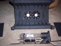
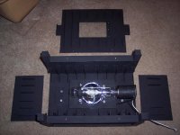
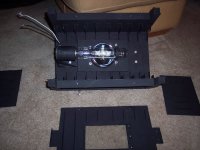
Here we go after all this time...
My light engine -
Those are 2 x 90mm 60CFM fans
Ushio S400D
Ikea 'Napkin' reflector
The "fins" you see throughout are aluminium angle riveted to 26 gauge sheet metal. In total, the fins more than double the surface area exposed to the moving air. This was a royal pain in the a$$ to make. It took me a LOT of hours to complete with only a Dremel and a pop rivet tool.
From my test thus far, no outside metal surface reached > 145F
A temp probe places ~ 240mm from the buisness end of the light engine where the LCD would be only read 88 degrees F.
I do believe it is going to work perfectly!
Attachments
- Status
- Not open for further replies.
- Home
- General Interest
- Everything Else
- The Moving Image
- DIY Projectors
- My ProView 15.4" 1280x800 HD project...