Hmmm, my idea was to try to make the traces in the lower field wider so to create more force than thinner in the higher field to get a more even force over the membrane - but as all traces are in series that don't work.
In order for that to work one ned to segment the traces into 2 or 3 branches and make these parallel. This will give you a 4 or 2 ohm driver which is not your spec.
//
hehe yeah thought about it as well a split second 🙂 until i thought about how current travels like a sewer system with big pipes and small ones.. big one after a small one will still flow the same water as the small one 🙂 since its in series. and the small one does not allow more water to flow 🙂
BUT if you could make 2 coils of 8 ohm . in parallel it would work like this. only problem is uneven power handling. as high as the thinnest tracks. but this way you could compensate for uneven field and still use the middle part.
its complicated but this would result in using you magnetic field the best way possible without changing whole magnet arrangement. it does get complicated 🙂
well if you use 2 coils one with wider trace for the weaker middle gap and smaller for the outer gaps. but hell its just an idea. it gets to complicated , also he wanted 8 ohms so.
its a bit like the discussion in the ribbon thread you know ? etching the outer edges more so more current flows in the middle.
like in your ribbon with traces on mylar you could use a thick trace in the the middle and 2 smaller ones on the outside (if the magnetic field was weaker in tje center) only problem is you cant put them in series with one and other. must be parallel. wich defeats the purpose usually of such cronctrustion when you want high ohm ribbon
Last edited:
oh TNT, thats weird, you where saying the same... its kinda weird i did not read that line. makes my post a bit overkill 🙂 haha sorry dude
I would personally build it like this with 2 coils and run it 4ohm...
I'm using digital xo and class D so no problem 🙂
Heck, I run em' 2 ohm :-D or double amps..
//
I'm using digital xo and class D so no problem 🙂
Heck, I run em' 2 ohm :-D or double amps..
//
oh TNT, thats weird, you where saying the same... its kinda weird i did not read that line. makes my post a bit overkill 🙂 haha sorry dude
No prob 😀
//
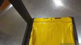
Well guys...picked up my test foils today!
Four pieces in all and very happy about it!
Took a couple photos of them.
Very well executed...just like i planned them.
Now i have to put some pressure on those CNC guys...
Four pieces in all and very happy about it!
Took a couple photos of them.
Very well executed...just like i planned them.
Now i have to put some pressure on those CNC guys...
Attachments
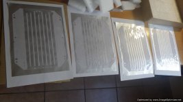

Unfortunately they are going to be yellow in the end...
I added the cds for scale...
I hope you like my selection!
I added the cds for scale...
I hope you like my selection!
Haha, weli thought kapton is yellow i think this is the Pe version. The final one will be yellow 🙂
Looks really cool. Fantastic 🙂
Have been playing with a planar some years ago Sensible Audio ... one hint with "push-pull" design ... be very carefull when putting the 2 sides together .... I used mags that where 2 mm thick you are using some monster ones ... there is really much force in play and they will try to missalign and pull together in the groves between the other mags on the opposite plate ... smack 😉
One thing I have been thinking about is how the power handling ability is affected by running the ends of the traces under the frame. It of course depends on how the diaphragm is mounted or glued to the frame ... but if it is done so it is no thermally conductive to the fram and therefore to metall and then air ... this will be the weak spot power wise. To have some damping I think I would use double sided tape to mount the diaphragm ..... not sure how much of a problem this will actually be ... just worth considering.
Looking forward to seeing the next steps 🙂
@ Baldin...nice remarks!
Great project! What happened then?
I know how easy it is to mis-align the frames when opening and closing!
I have my fair share of opening and closing various planars and have noticed
how difficult is to keep them exactly opposite when they are coming close OR pulling away!
I have made myself a certain type of "guide" that is very effective in securing just that.
Just some pieces of MDF and careful placement and there is NO WAY something bad it's going to happen.
See pics below.
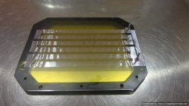
As for the traces running under the frame...it is very much widely used and have seen it again and again so i imagine there is no obvious problem.
Again see pics.
I imagine that the diaphragm is an air cooled motor as it has a gigantic ratio with direct air contact...therefore that portion is acting as a intercooler (car term!) for the whole area.
On the gluing area i will probably use a really thin layer of double sided sticky tape (for PE foil only).
Not fancy but with the pressure applied from the clamping screws all around it will hold.
I am excited too!
Great project! What happened then?
I know how easy it is to mis-align the frames when opening and closing!
I have my fair share of opening and closing various planars and have noticed
how difficult is to keep them exactly opposite when they are coming close OR pulling away!
I have made myself a certain type of "guide" that is very effective in securing just that.
Just some pieces of MDF and careful placement and there is NO WAY something bad it's going to happen.
See pics below.
As for the traces running under the frame...it is very much widely used and have seen it again and again so i imagine there is no obvious problem.
Again see pics.
I imagine that the diaphragm is an air cooled motor as it has a gigantic ratio with direct air contact...therefore that portion is acting as a intercooler (car term!) for the whole area.
On the gluing area i will probably use a really thin layer of double sided sticky tape (for PE foil only).
Not fancy but with the pressure applied from the clamping screws all around it will hold.
I am excited too!
Attachments
-
 Photo0201-Optimized.jpg85.2 KB · Views: 230
 -
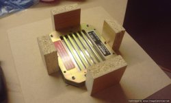 Photo0200-Optimized.jpg84.8 KB · Views: 244
 -
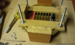 Photo0179-Optimized.jpg95.4 KB · Views: 230
 -
 Photo0169-Optimized.jpg78.9 KB · Views: 224
 -
 20150506_201825-Optimized.jpg106.1 KB · Views: 257
 -
 20150610_193825-Optimized.jpg117.5 KB · Views: 189
 -
 20150610_193848-Optimized.jpg92 KB · Views: 175
Last edited:
Color of course irrelevant. The 2 CDs are unknown to me.
//
Well...it's Tori Amos's Strange Little Girl and Porcupine Tree's In Absentia...
Here's a taste:
https://www.youtube.com/watch?v=ghGgycFEg64
and
https://www.youtube.com/watch?v=0UHwkfhwjsk
Plenty more of those in their work.
Thanks. Well ... normal life and work happened ..... really want to take this up again .... plan was for a line array type of thing with a sub under 100 - 200 .....@ Baldin...nice remarks!
Great project! What happened then?
.......
You are probbly right about the heating not being a real problem ... especially not for non PA use.
Good to see you are in control with the jig ... looks good.
Question: the spacers between top/bottom plate and diaphram ... what is the material you plan to use?
I'm still considering what to use ... used thin wood in the proto .... not so easy to work with and get nice ... (only 5 mm thick) ... and not the best material to bond with the plastic material of the diaphram .....
Do you have acces to alu/mylar film ?
I have some 160mm wide ,15my alu and 7my.mylar.Mylar light blue
I dont use it. I use a sandwich with 10my alu and adhesive mylartape.
Bernt
I have some 160mm wide ,15my alu and 7my.mylar.Mylar light blue
I dont use it. I use a sandwich with 10my alu and adhesive mylartape.
Bernt
Last edited:
bandsei, i got some of that from you (really thanksfull for that !). it is really nice! stuff. do you know what etch resists stays on ? i tried doing some etching but the resists that works on copper just comes off the aluminium 🙁
WrineX, try acrylic paint as a resist and use a copper sulfate/table salt mordant for aluminum. Isopropyl or denatured alcohol to remove the dried paint after etching.
http://www.nontoxicprint.com/etchzincsteelaluminum.htm
http://www.nontoxicprint.com/etchzincsteelaluminum.htm
- Home
- Loudspeakers
- Planars & Exotics
- My own magnetic planar driver