I'm now inclined to make a classic VAS (enhanced for trial's sake) with a TMC using the same OPS as I've been using, as well as the same voltages etc to make it as close as possible for comparission, to compare THD.
Harry, no; C3 was part of a snubber that's now gone again.
Sorry, should have been clearer:
I was talking about C3 in the schematic from post #79.
Yeah that's correct, that's the Cmiller.
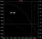
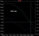
I now have a version with TMC and I can clearly see the increase in slope on the gain plot, but the phase remains icky. I'm now testing phase margin with a pure capacitive load.
I now have a version with TMC and I can clearly see the increase in slope on the gain plot, but the phase remains icky. I'm now testing phase margin with a pure capacitive load.
Yeah that's correct, that's the Cmiller.
Right. So you could have changed ULGF by changing the capacitor's value as well as by degeneration of the input stage.
Don't forget that you need to do a bode plot of the miller loop as well as the global loop.
Ditto if you're sticking with TMC. I believe that with TMC one plot should look second-order and another should look first order. Both need to have decent stability margins.
Last edited:
Right. So you could have changed ULGF by changing the capacitor's value as well as by degeneration of the input stage.
Don't forget that you need to do a bode plot of the miller loop as well as the global loop.
Ditto if you're sticking with TMC. I believe that with TMC one plot should look second-order and another should look first order. Both need to have decent stability margins.
You can have it with one shot, just do a bode plot of the global loop and connect TMC resistor after the Tian probe.
Hi Guys
This VAS is actually interesting!
Do you have a souped up Audio Precision system to measure a real product with? Are there measurements or just sims?
Have fun
Kevin O'Connor
This VAS is actually interesting!
Do you have a souped up Audio Precision system to measure a real product with? Are there measurements or just sims?
Have fun
Kevin O'Connor
Nah I don't, but I can wish =) So far the measurements are just sims and the results are used as a guideline, not an absolute.
I've given my VAS a little break as I'm now at a point where I don't know well how to continue:
On one end, with a simple miller compensation from VAS-out to VAS-in of 56p, (and a small tweak to the buffer local feedback (82pf with 22Ohm series) I can get it rock stable. The THD is very bad this way; around 0.01%. When I take out the OPS and put back in an ideal OPS, the THD is back to 0.000055%.
It's clear that the OPS is the main contributor to THD and when excluded from the feedback, it rears its head bad.
If I use OPS inclusive feedback, I get this extra phase shift which leaves me with a phase margin of less than 30 degrees on two locations in the band. This is not acceptable.
So. I think I'm stuck. Using plain miller defeats the purpose of this VAS as I throw away all that loopgain.
I've tried TMC, TPC and variants, but no matter, where there is improvement in gain, there's a degradation in phase.
Using plain miller defeats the purpose of this VAS as I throw away all that loopgain.
That's what compensation does in all circuits! You have to get the loop gain to cross zero before all your high-frequency singularities kick in and bring their evil phase shift.
haha yeah, I've experimented with this schematic like a mad-man. I think I made some improvements though. I now have a combination of both Cherry and TMC with the C/R path from VAS out to OPS out is rather low-ohmic.
The question though is what an acceptable phase margin is. When I assume the OPS series resistance (regardless of Cload) is at least 50mOhms, I can get so much more performance from the circuit than if I would stabilize it for an ideal C.
In this situation I now have around 0.000023% into 8Ohm and 0.000046% into 4Ohm. As long as the series resistance doesn't drop below 50mOhm it remains stable at all capacitances (within sensible range as they still load the OPS).
So what's practical?
You'll never get a perfect piece of wire so there will always be some resistance. In my sims I assume a series resistance of 0.1R with a C load (without output filter). I feel that is extreme enough. Also, you will probably have an L//R filter on the output.
Any chance you could post an updated schematic?
Paul
Any chance you could post an updated schematic?
Paul
Yes, please provide some examples.
A schematic with a c load and bode plot showing low margins, what you did to improve the margins, and what bode plot that resulted in. Then repeat but with your added series R. Presumably you do have an L/R on the output before the load?
A schematic with a c load and bode plot showing low margins, what you did to improve the margins, and what bode plot that resulted in. Then repeat but with your added series R. Presumably you do have an L/R on the output before the load?
Maybe this is the wrong approach but for sim purposes I prefer not to use an output filter. An output filter should be used for a real circuit but would it not obscure simulation results?
An output filter should be used for a real circuit but would it not obscure simulation results?
Depends on what you mean by "obscure" and "results". If you're talking about closed-loop response, then I usually measure that with an output network in place and look at response both before and after the filter.
With loop-gain simulations, you should also have the output network in place. The whole point of the output network is to help achieve stability into capacitive loads without having to severely compromise loop gain.
Last edited:
Minor correction to earlier post:
That's what compensation does in all circuits! You have to get the loop gain to cross zero dB before all your high-frequency singularities kick in and bring their evil phase shift.
Depends on what you mean by "obscure" and "results". If you're talking about closed-loop response, then I usually measure that with an output network in place and look at response both before and after the filter.
With loop-gain simulations, you should also have the output network in place. The whole point of the output network is to help achieve stability into capacitive loads without having to severely compromise loop gain.
I need to learn to be more precise in my posts.
For extreme load testing I put the load before the filter though.
Although, I haven't been looking at the results after the filter. Should do that really.
Last edited:
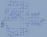
Alright guys, here an updated schematic. It's the 200W/4Ohm version that I intend to proto.
C10 (33p), R33 (56R), C22 (680p) and R38 (330R) are what makes up the TMC network. C31 (33p), together with the buffer local networks C1, C4 (82p), R37, R39 (82R), form the Cherry style network.
It's stable with a minimum series R of 50 mOhms. Here's the THD:
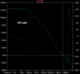
I think it's pretty good after all; I can chose to increase the TMC influence by increasing C10 to improve stability without sacrificing too much THD.
Something noteworthy is that the phase dips beyond 180 degrees mid-way band don't impact stability. It's where OLG == CLG where OLG phase becomes the determining factor, at least that's what I conclude from this 🙂
C10 (33p), R33 (56R), C22 (680p) and R38 (330R) are what makes up the TMC network. C31 (33p), together with the buffer local networks C1, C4 (82p), R37, R39 (82R), form the Cherry style network.
It's stable with a minimum series R of 50 mOhms. Here's the THD:
Code:
[SIZE=2]N-Period=1[/SIZE]
[SIZE=2]Fourier components of V(x)[/SIZE]
[SIZE=2]DC component:-0.0105172[/SIZE]
[SIZE=2]Harmonic Frequency Fourier Normalized Phase Normalized[/SIZE]
[SIZE=2]Number [Hz] Component Component [degree] Phase [deg][/SIZE]

[SIZE=2]1 1.000e+03 4.000e+01 1.000e+00 179.98° 0.00°[/SIZE]
[SIZE=2]2 2.000e+03 4.291e-06 1.073e-07 19.53° -160.44°[/SIZE]
[SIZE=2]3 3.000e+03 8.081e-06 2.020e-07 20.44° -159.53°[/SIZE]
[SIZE=2]4 4.000e+03 1.920e-06 4.800e-08 -128.56° -308.54°[/SIZE]
[SIZE=2]5 5.000e+03 4.482e-06 1.121e-07 -139.40° -319.38°[/SIZE]
[SIZE=2]6 6.000e+03 1.124e-06 2.811e-08 55.93° -124.05°[/SIZE]
[SIZE=2]7 7.000e+03 2.903e-06 7.258e-08 58.38° -121.60°[/SIZE]
[SIZE=2]8 8.000e+03 7.815e-07 1.954e-08 -128.16° -308.14°[/SIZE]
[SIZE=2]9 9.000e+03 2.120e-06 5.301e-08 -104.80° -284.78°[/SIZE]
[SIZE=2]10 1.000e+04 5.741e-07 1.435e-08 47.54° -132.44°[/SIZE]
[SIZE=2]Total Harmonic Distortion: 0.000028%[/SIZE]
I think it's pretty good after all; I can chose to increase the TMC influence by increasing C10 to improve stability without sacrificing too much THD.
Something noteworthy is that the phase dips beyond 180 degrees mid-way band don't impact stability. It's where OLG == CLG where OLG phase becomes the determining factor, at least that's what I conclude from this 🙂
Attachments
Last edited:
P.S. if you'd like to see specific plots just ask and I'll try to come up with them.
Edit: The output inductor with its parallel resistance still needs to be added. That might very well be a 'guard' against unrealistic loads. I'd have to see how such an output filter would influence stuff.
Edit: The output inductor with its parallel resistance still needs to be added. That might very well be a 'guard' against unrealistic loads. I'd have to see how such an output filter would influence stuff.
Last edited:
Hang on, are these open-loop-gain plots or loop-gain plots? It's the latter that determine stability.
- Status
- Not open for further replies.
- Home
- Amplifiers
- Solid State
- My New VAS Topology