Erhm.. these are open loop gain plots. Did I do it wrong? They should have been closed-loop plots? Or is this "loop-gain" you speak of a 3rd, different kind of looking at things 🙂
I was pointed by keantoken to the example loop gain in the examples folder of LTspice.
" /examples/educational/loopgain2.asc in your LTSpice folder"
" /examples/educational/loopgain2.asc in your LTSpice folder"
Erhm.. these are open loop gain plots. Did I do it wrong? They should have been closed-loop plots? Or is this "loop-gain" you speak of a 3rd, different kind of looking at things 🙂
You have my paper on two pole compensation, yes?
Observe Figure 1, with blocks that have transfer functions of G(s) and H(s). Open-loop-gain is G(s), and loop-gain is G(s)H(s). Closed-loop gain (for an inverting configuration such as yours) is [G(s)*(H(s)-1)]/[1+G(s)H(s)].
What you need for stability analysis is the bode plot of G(s)H(s).
Ah gotcha. I'm not a math buff; Putting your comment and mcd99's together it's probably right to say that the loopgain2.asc example shows G(s)H(s). So you're looking at the right graphs, I was just wrong calling them OLG.
That's what I'm using to determine the loopgain. (See Vi and Ii at the output).
So I see, sorry missed that. The question I have is that is it in the right place with regards to the TMC? I don't know the answer, just wondering (This question is as much for my benefit 😉)
So you're looking at the right graphs
Good.
Yes, you are correct that phase dips below -180 when loop-gain is greater than 0 dB are ok as long as the phase "recovers" back to something greater than -180 (minimum phase) at the point where loop-gain crosses 0 dB (as shown in your graphs). Personally I find this deeply non-intuitive and am yet to read a good explanation as to why this is so. For now I just accept it as true.
I find the loop-gain plot with 100 nF a bit scary. Gain margin is very low. Presumably this improves with an L/R output network?
So I see, sorry missed that. The question I have is that is it in the right place with regards to the TMC? I don't know the answer, just wondering (This question is as much for my benefit 😉)
Hopefully dadod is still reading the thread and can tell us.
The plots look high order so I guess so, but you've got the extra complication of more feedback loops.
You need to be 100% confident that the stability of all feedback loops have been adequately investigated.
An output inductor improves matters significantly regarding load tolerance. With the same configuration I can now clear the load cap's ESR (obviously). This leads me to the question, how much compensation do I still need? If I can remove everything but the Cherry comp, I'll be able to get maximum performance from the circuit.
An output inductor improves matters significantly regarding load tolerance. With the same configuration I can now clear the load cap's ESR (obviously). This leads me to the question, how much compensation do I still need? If I can remove everything but the Cherry comp, I'll be able to get maximum performance from the circuit.
Please closely read page 8 of my paper. And this from earlier in the thread:
Now that you can do the loop gain plot, you can try doing it at different operating points. For example, you can try different DC operating points by AC-coupling the load with a large capacitor (e.g. 1 kF) and then adding some DC bias to the input signal. This will adjust the DC-voltage operating points of the circuit without also increasing the output current. You can also test at different current levels by adding an ideal current source from the output to ground [again, the load needs to be AC coupled].
If you get stable operation with all of these scenarios (all with a variety of unpleasant loads), you're probably ok. You will probably find that in order to have any margin at all with unpleasant combinations of voltage, current and load, margins under more benign conditions need to be quite large (70 degrees or more phase margin and 10 dB or more gain margin are what I would consider to be "quite large").
Last edited:
You need to be 100% confident that the stability of all feedback loops have been adequately investigated.
Take it you apply the same stability criteria to the other loops as the main loop. And you just break the loops in sensible places.
I can't get my head round the TMC aspect of the main loop and how it affects the break point used for analysis.
Loop unstable
Dear Magicbox,
very interesting design.
Loop is currently unstable due to phase shift > 240 degree.
Hope you get the loop stable. Attached the current schematics with "TianProbe()" function in "plot.defs". Initial asc file was from post #83.
I have added my functions so you are able to do many measurements with a simple "uncomment/comment" a block. For more information about SOA, OLG, LG, PM, GM, FFT have a look at:
http://www.diyaudio.com/forums/soli...ormance-class-ab-power-amp-200w8r-400w4r.html
There you can find many design hints which may help.
BR, Toni
Attachments
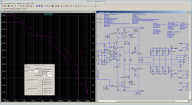
I don't get how your loopgain starts out at over 160dB while on my end it's 125dB. I'm using the exact same function in the plot.defs and the same setup of Vi and Ii.
Hopefully dadod is still reading the thread and can tell us.
The plots look high order so I guess so, but you've got the extra complication of more feedback loops.
You need to be 100% confident that the stability of all feedback loops have been adequately investigated.
In my opinion MagicBox did loop gain correctly. If done in that way it looks like TPC loop gain(as it should be). Certainly local loop gain plot could help too.
I never have stability proble with the real amp after this kind of TMC loop gain simulation.
By the way if MagicBox activate grid and Anravel Branch Wrap in his Waveforms it'll be more readable.
By the way if MagicBox activate grid and Anravel Branch Wrap in his Waveforms it'll be more readable.
I prefer the discontinuity in the phase plot, because it's then immediately apparent where 180 degree phase shift happens. Agreed on the grid.
I don't get how your loopgain starts out at over 160dB while on my end it's 125dB. I'm using the exact same function in the plot.defs and the same setup of Vi and Ii.
Please submit your asc file for a comparison.
BR, Toni
So far in my simulations it remains stable with different C loads when I use an output filter. Even when I disconnect all but the Cherry compensation it remains stable. It yields 0.000005% THD though. I don't know how much of this is reliable though, regarding stability.
You need to be 100% confident that the stability of all feedback loops have been adequately investigated.
You dont really need to, inspection of the closed loop response is enough. If there is adequate PM and GM and no peaking in the closed loop response there is no need for further investigation of any other feedback loops as these would manifest themselves in the closed loop response.
- Status
- Not open for further replies.
- Home
- Amplifiers
- Solid State
- My New VAS Topology