There is another mistake Sylvain ... you have 2 cap named as C35 (upper left corner ). The first one is C34
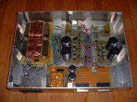
Completed external power supply, fully dual mono with 2 DB25 Outputs including +/-Digital Supply if needed by an other Pass Labs preamp for example. It is split in 4 PCB done over a few months. The Transfo PCB, the Digital Supply and Output PCB and the two (Left and Right) +/-40V Pre-Regulator PCBs.
The is a CL-60 thermistor inrush current limiter, an other one use as Ground Loop breaker and an EMI filter with integrated power-on switch and fuse. A blue led Power-On Indicator complete the supply. It is big, tough and heavy...😀
Bye...
The is a CL-60 thermistor inrush current limiter, an other one use as Ground Loop breaker and an EMI filter with integrated power-on switch and fuse. A blue led Power-On Indicator complete the supply. It is big, tough and heavy...😀
Bye...
Attachments
Regarding my last e-mail....
Algar, Look carefuly to your schematic and this one from Ono Service Manual...
Algar, Look carefuly to your schematic and this one from Ono Service Manual...
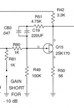
I'm fine tuning and testing my ONO preamp. My schematic now contains a lot of voltages at all the circuit junctions. It can be use to test and troubleshoot the ONO.
Reading the "ONO Group Buy" thread I found some few things that were perfectly set into my own ONO. The voltage at R67 & R53 was in my case 1.2V instead of the 1.0V specified on the original PassLabs schematic. I always wonder what was causing this difference. Reading the thread I learned that it is cause by the red led D5 type.
I installed socket pins at D5 and tried more than 10 different leds when I finally got the correct voltage of 1.0V.
Also I found that it was difficult to fine tune the DC offset of both the non-inverting and the inverting outputs since the none-inverting offset is causing the inverting one to change. So I installed a jumper (JP1) that I can remove to isolate the inverter. I adjust its own offset using R59. Then I plug-in JP1 and I have just to adjust the non-inverting DC offset using R4.
Some users suggested to change R57 from 221R to 499R to reduce the power dissipation of Q20-22 that are really too hot. It works well to keep the fets cooler, but by doing so, I was no longer able to adjust correctly the inverter DC offset to zero. Maybe it is because Q8 and Q19 are not matched at all. Anyway, I kept R57 to 221R and installed small heatsinks on Q20-22
I put some instructions on the schematic on how to do the adjustments. I mentionned also that D5 should be selected to get the correct 1V voltage.
Finally, since the power supply contains a lot of capacitance and charge rather slowly, I changed the Mute PCB timing capacitor C40 from the original 220uF to 470uF to increase the Mute delay to let the supply stabilize.
Have fun.
Attachments
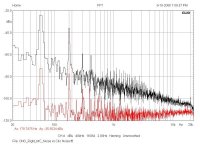
I used WinClio to measure my ONO. Not too bad.
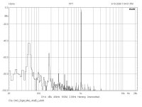
This is the noise floor of the MC input in Black. The Clio system own noise is in Red. Big spikes at 60 and 180Hz are caused by the Clio system mounted inside a PC.
The curve is showing the inverse RIAA gain curve. More gain in the low, going down in the highs...
This is the noise floor of the MC input in Black. The Clio system own noise is in Red. Big spikes at 60 and 180Hz are caused by the Clio system mounted inside a PC.
The curve is showing the inverse RIAA gain curve. More gain in the low, going down in the highs...
Attachments
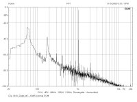
This is the MC Input. Noise is higher at about -80dB.
Again the inverse RIAA gain curve is shown.
Measured at Vin=-60dB (1mv) and -75dBV (170uV), 1Khz
Gain= 58.4dB (J1,2 IN), 63.6dB (J1 out), 71dB (J1&2 out)
(Specs 76 dB). I'm using SK170GR
THD = 0.04%
IMD = 0.03%
Again the inverse RIAA gain curve is shown.
Measured at Vin=-60dB (1mv) and -75dBV (170uV), 1Khz
Gain= 58.4dB (J1,2 IN), 63.6dB (J1 out), 71dB (J1&2 out)
(Specs 76 dB). I'm using SK170GR
THD = 0.04%
IMD = 0.03%
Attachments
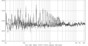
To see really the noise level of the MC section just by itself, I tought to measure the output of the MC section alone. Also I decided to remove the CLIO card noise floor from the data.
To do so, I sampled the card noise floor and export the data. Then I did the same for the MC section itself. Then using Excel, I imported both data, then substracted the noise floor data. To get the best resolution, selected the highest FFT resolution. It is slow but more precise.
So now this graph is the noise floor of the MC section alone. It is mostly lower than -120dBV, or 1uV and a average of -150dBV.
The XONO user manual specs -90dB reference to 1mv(-60dBV), so it is 90+60 = -150dBV. So my result is very close to the real XONO, not bad 😎
Attachments
Finally I did a big zip file that contains all the project needed files, schematics, parts list and PCB. It is about 3.6Mb.
Ask me by email if you like a copy.
Have fun.
Ask me by email if you like a copy.
Have fun.
I received today an other batch of 2SK170GR and was finally able to replace the defective fet into the left channel matched quad. By the way, this defective fet had an Ids of 170ma instead of the original matched value of 25ma! The problem it was causing is a 60hz noise that was floating around, going out and in into a random pattern. The MC stage should be perfectly silent when working correctly, this one was not. But it is fixed now. 😎
I put the preamp all back together and for the first time I was able to listen to my completed XONO. The sound is, in just one word, WOW!!!
It is incredible, full of dynamic and impact. I'm using the MC input set at 16dB of gain and the preamp is perfectly silent. No noise even at maximum volume. Music flows with rythm and ease. This is the best phono stage I ever heard by far. I'm presently listening to one of my Steely Dan album and the sound blows away any CD version of it. The is hifi even
Thanks again Mr. Pass and Mr. Wayne Colburn for this great design and sharing it with us. I'll post my project to www.passdiy.com pretty soon.
If you like vinyle, please build the preamp. It is a big and complex project but very rewarding.
As I mentionned the project files are big. If you're asking for the files, check and empty you email often so the files get throught.
Bye...
SB
Bye...
SB
- Status
- Not open for further replies.
- Home
- Amplifiers
- Pass Labs
- My new Aleph ONO Phono Section