Post in thread 'SSR for speaker protection?' https://www.diyaudio.com/community/threads/ssr-for-speaker-protection.318946/post-5345287

this exactly the reason why i go not the way of UPC1237...Thimios,
Where do you get legit UPC1237’s?
if i remember right that Jhofland made a smaller /tiny SSR?
aaaahh....found it......geoffw1 did a SSR:
here:
That's why I choose this ssr by LKAThimios,
Where do you get legit UPC1237’s?
No need for a upc1237.😉
?
This IC is in the schematic....?
PS. Ah...i get it....the first post did not show the latest version
This IC is in the schematic....?
PS. Ah...i get it....the first post did not show the latest version
Last edited:

🙂
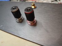
i have different ones. it should be Rhodium...but i do not care- i want to try different ones
binding posts
i have different ones. it should be Rhodium...but i do not care- i want to try different ones
binding posts

Hi
after a heavy cold i am back again...slowly...
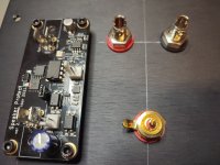
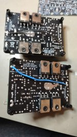
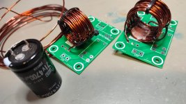
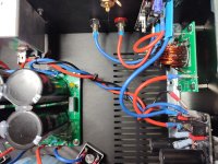
done:
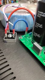
1 Thiele network- coil and resistor
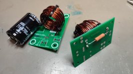
my first big coil without having a pole is annoying😒. i use a cap 71V 4700µF . this has the right size. 😉 i tried to "fix" the coil with tape or with heat gun but finally i use cable stripes.. looks bad but it works. i get 4,9µH...
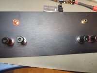
wiring SSR to LS posts
it was not possible to solder on that kind of LS posts..... . they have a strange surface i use the set screw
Input GND to power GND
R26 0,22R soldered.
cut out the parallel resistor to R27 to get with 32V enough current for DC servo. PSU will be 42V
kr
chris
after a heavy cold i am back again...slowly...
done:
1 Thiele network- coil and resistor
my first big coil without having a pole is annoying😒. i use a cap 71V 4700µF . this has the right size. 😉 i tried to "fix" the coil with tape or with heat gun but finally i use cable stripes.. looks bad but it works. i get 4,9µH...
wiring SSR to LS posts
it was not possible to solder on that kind of LS posts.....
. they have a strange surface i use the set screwInput GND to power GND
R26 0,22R soldered.
cut out the parallel resistor to R27 to get with 32V enough current for DC servo. PSU will be 42V
kr
chris
Attachments


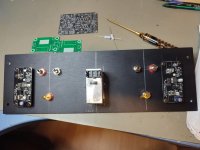
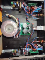
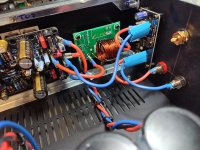
next step.
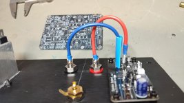
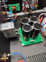
i am not really lucky with the rail cabling and the amps output cabling... 🤔
also the power plug and the filter is too big....🤔
open issues:
signal cabling prepared.
earth connection
NTC + power AC secondary cabling
kr
chris
i am not really lucky with the rail cabling and the amps output cabling... 🤔
also the power plug and the filter is too big....🤔
open issues:
signal cabling prepared.
earth connection
NTC + power AC secondary cabling
kr
chris
Attachments
-
 power plug with filter too big_1.jpg556.8 KB · Views: 79
 -
 inside_2.jpg632 KB · Views: 70
 -
 inside_1.jpg610.5 KB · Views: 80
 -
 amp inside.jpg480.7 KB · Views: 77
 -
 ampout_coil_SSR_LS_1.jpg484.9 KB · Views: 76
 -
 ampout_coil_SSR_LS_2.jpg531.5 KB · Views: 71
 -
 ampout_coil_SSR_LS_and rails cables_1.jpg572.4 KB · Views: 79
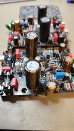
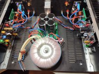
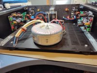
transformer mounting upwards is not possible because housing is 3U/300mm and the transformer has more then 130mm diameter 🙄
have to check for a different cap bank....
have to check for a different cap bank....
Hi
i re check my PCB for cap banks ore similar...no chance.
but
i see at post 1761 by Vunce that he has mounted his prasi CRC and the transformer side by side.
no idea which VA his transformer .
i am a friend of big caps too --> less ripple..
what is "needed" for a 70W/8R amplifier? my roughly estimation is :
70W at 8R 2x for both channels 140VA --> 160 VA transformer + 50% reserve 250VA
what rating is needed for 4R?
kr
chris
Last edited:
70 watt @ 4 ohm is approx 6 amps peak load current per channel which gives an average of 1.9 amps per channel. Call it 2 amp. Two channels would be 4 amp. 4amp average current at a secondary voltage of 28 volts is 112 VA. Times two for both windings gives 224 VA. So 250 to 300 VA.
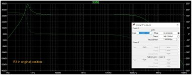
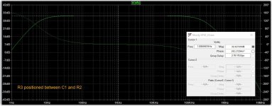
Revisiting post 1475 on the bump in the low end frequency response. I found that moving R3 so that is it before R2 seems to address this.
The tradeoff seems to be a -3dB point around 7Hz and about 1.2db less overall gain. Settling time does not seem to be affected. Not sure if this reduces the servo's authority.
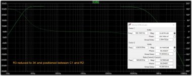
R3 can be reduced from 4k7 to 3K which gives a -3dB point around 5Hz and the gain reduction decreases to about 0.8db.
The tradeoff seems to be a -3dB point around 7Hz and about 1.2db less overall gain. Settling time does not seem to be affected. Not sure if this reduces the servo's authority.
R3 can be reduced from 4k7 to 3K which gives a -3dB point around 5Hz and the gain reduction decreases to about 0.8db.
Attachments
- Home
- Amplifiers
- Solid State
- My MOSFET amplifier designed for music