Be careful of the derating of SMD resistors, they only can radiate to air on one side, pay attention to their derating curves.
Thanks Nico, I'll do the sums on these as wellBe careful of the derating of SMD resistors, they only can radiate to air on one side, pay attention to their derating curves.
What I do if I have the real estate is have a cleared copper under the resistor and use a little solder paste to aid in heat dissipation onto the copper below it. Also you can increase solder pad size to act as heat spreaders. But then what is the point of making small smd pc boards.😳

I have seen some of Hugh Dean (AKSA) designs where he uses a few resistors in parallel to increase the heat dissipation properties. If it is a double side through hole plate you can use both sides for the parallel resistors and save a little space.
Running power dissipation calculations using Mooly's sim for 70W 1KHz, the dissipation for the resistors I've currently got as 1206 film resistors are all well below their rated 0.25W figures. If I went SMD for the power resistors it would be a different story. If it were a problem, I would probably go with mini-MELFs.
The SOT-89 sounds like it will work. Check the size of the pour for the collector. Bigger is better for heat dissipation.
Working on collector pour right now. I've already tweaked the layout around Q3/Q5 to allow larger(slightly) heat spreader zones and looking at the relevant derating that comes with that. I've also moved the gate resistors much closer to the MOSFETs.
More soon🙂
More soon🙂
I meant the Power Resistors only. Others are fine. 1206 is easy to work with since they are pretty large, much better than 0805.
I seen people cutting the gate short and mount the gate resistors directly to the gate to supress any possibility of oscillation
I'm normally working with 0805s on my preamp, phono and logic circuitry so 1206 are like huge tombstones! I've gone with 1206s to give large margins on voltage limitsI meant the Power Resistors only. Others are fine. 1206 is easy to work with since they are pretty large, much better than 0805.
Almost all my designs use Lateral Mosfets and I seldom use gate resistors and just a squigle in the gate tracjk is mostly enough inductance to supress most problems. In a very bad case I slipped ferrite beads onto the gate.
My current layout has the gate resistors either right by the gate pins or as close as I can get. The furthest one away is still closer than Prasi's THT version.I seen people cutting the gate short and mount the gate resistors directly to the gate to supress any possibility of oscillation
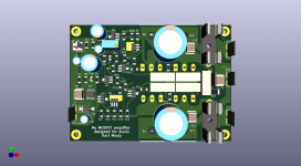
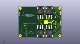
Layout with increased heat spreaders for Q3/Q5 and gate resistors now located close to MOSFET gate pads. Heat spreaders and output tracks now have solder mask adjusted to aid heat dissipation. Also included some text.
Attachments
Almost all my designs use Lateral Mosfets and I seldom use gate resistors and just a squigle in the gate tracjk is mostly enough inductance to supress most problems.
Do you mean something like these squiggles?
Reminds me of my microwave amplifier stuff back in the day...Do you mean something like these squiggles?

For the heat dissipating copper pours, you could add a larger pour on the bottom side with via stitching to transfer the heat. Just a though since it looks like there aren't any tracks on the bottom to interfere.
With SOT-89 and the current extra copper pour I think we're fine. As you say, there aren't any tracks on the bottom to interfere but my concern would be parasitic coupling to other components in the region.
It worked did it not? Besides it saved money in components 😉🙂Reminds me of my microwave amplifier stuff back in the day...
- Home
- Amplifiers
- Solid State
- My MOSFET amplifier designed for music