Hi Aditya,
I did not receive your mail. Might have caught by spam filter. Pl send your number on mail again.
I did not receive your mail. Might have caught by spam filter. Pl send your number on mail again.
Mr Elvee,
I would request you to please reply to my following academic question.
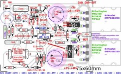
Will there be any benefit of combining input and feedback ground together and floating it through a resistor of typically 10R resistor from the power ground?. The question is possible elimination of Earth Loop if any. The present build has already very very low 50 Hz Hum with input short almost dead silent. Will this arrangement reduce 50 Hz hum further?. I have not yet practically tested it. I need your expert advice on this issue as you have not done this in your original schematic at Post # 1.
The snapshot of modification is attached.
Elektor Elektronics in its "Mini Cresendo" Amplifier has done this in past.
Thanks
Rajesh Katiyar
I would request you to please reply to my following academic question.
Will there be any benefit of combining input and feedback ground together and floating it through a resistor of typically 10R resistor from the power ground?. The question is possible elimination of Earth Loop if any. The present build has already very very low 50 Hz Hum with input short almost dead silent. Will this arrangement reduce 50 Hz hum further?. I have not yet practically tested it. I need your expert advice on this issue as you have not done this in your original schematic at Post # 1.
The snapshot of modification is attached.
Elektor Elektronics in its "Mini Cresendo" Amplifier has done this in past.
Thanks
Rajesh Katiyar
Attachments

Last edited:
Yes, it can help with ground-loop issues, and I think that one of the contributors to this thread included the option in his PCB project
2nd Anniversary
Hi Elvee,
Thanks for your Circlophone designs, I have 3 amplifiers providing sweet music for 2 years now. I have retired my other diy amps, so its endgame for me.
Hi Elvee,
Thanks for your Circlophone designs, I have 3 amplifiers providing sweet music for 2 years now. I have retired my other diy amps, so its endgame for me.
Dear Mr Elvee,
Though the reply does not necessarily pertain to me yet I want to correct you for your comments "customer". In my openion no one is your customer all are your followers. You have given your Circlophone design absolutely free to all boarders with out taking any royalty at all. Also you were kind enough and ready all the time to answer and resolve to the querries of all boarders.
I too have discarded all of my previous made chip and discrete amplifiers as they do not stand before the performance of Circlophone.
I dont know why I prefer MOSFET version over BJT version may be because of its simplicity. The performance appear to be the same. I have decided to make another HEXFET Circlophone with 50-0-50 rail voltage using Bootstrap circuit suggested by you with IRFP240 OP devices in days to come. I have started procuring components for the same.
Thanks
I have decided to make another HEXFET Circlophone with 50-0-50 rail voltage using Bootstrap circuit suggested by you with IRFP240 OP devices in days to come. I have started procuring components for the same.
Some people build "amplifiers" but I build Circlophones.
It seems that you acquired the same hobby as mine.
Exactly Mr Terranigma. Lets's all enjoy it. Done lots of iterations in the component values of Circlophone schematic but found original schematic most optimum and stable.
Hi Junm,
i jump in to answer 🙂.
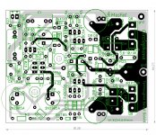
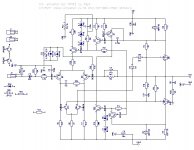
You can compare the schematic to the original one.
Mostly parts are same.
Mine is not fully build now on revisited board. 🙁
Feel free to use if you like.
Regards.
i jump in to answer 🙂.
You can compare the schematic to the original one.
Mostly parts are same.
Mine is not fully build now on revisited board. 🙁
Feel free to use if you like.
Regards.
Attachments
Hi terranigma, do you have the base schematic of this hexfet board?
I suggest you to follow Bangla H's version since it is available as gerber by Bangla H. Drilling alone is a most sensible reason for ordering PCB's instead making own.
Hi Junm,
i jump in to answer 🙂.
You can compare the schematic to the original one.
Mostly parts are same.
Mine is not fully build now on revisited board. 🙁
Feel free to use if you like.
Regards.
Thank you for fast response. That would be not easy for me to find the actual post which includes original PDF files. As I mentioned at up, ordering PCB's makes more sense if a gerber version is available.
If you follow the thread recently, can you add the bootstrap circuit as an option? It makes the rail-to-rail swing is attainable on MOS version.
Thanks.
Please refer post#2139 for bootstrap circuit I used in HEXFET version. Mr Elvee suggested BAT in place of resistor R26.
Thanks, yet another happy customer!
Yes, happy customer indeed. Any genius amp brewing in your lab?
No, not for the moment: I have a number of stubs hibernating in my files, but they would still need a lot of work before something concrete emerges
Hi Bangla, big thanks for your help, i have boards of this one but cant find the base schematics, i want to try this since i have several hexfets and vertical fets. I also have Laterals k134, k 1058 but i think it will not suitable maybe due to low Vgs . but a little adjustment on bias component will do,Hi Junm,
i jump in to answer 🙂.
You can compare the schematic to the original one.
Mostly parts are same.
Mine is not fully build now on revisited board. 🙁
Feel free to use if you like.
Regards.
@Elvee , what components to be adjusted in order that this will work with laterals except for the pin connections?
In principle, you just need to adjust the value of the G-S resistors.@Elvee , what components to be adjusted in order that this will work with laterals except for the pin connections?
The compensation components might need some optimization too.
- Home
- Amplifiers
- Solid State
- ♫♪ My little cheap Circlophone© ♫♪