Mr Elvee, While increasing input frequency to 10Khz at input signal of simulation, the THD increases dramatically. What could be the reason or am I doing something wrong?.
BJT softcopy
Hi Katiyar,
Did you see the message on previous page for the PCB maker, also the file in the post you suggested was for HExFet. I wanted your BJT softcopy.
Regards
Aditya
Hi Katiyar,
Did you see the message on previous page for the PCB maker, also the file in the post you suggested was for HExFet. I wanted your BJT softcopy.
Regards
Aditya
@aditya, you can also take a look at Bangla H's gerber files starting from post #1793. These ones are two layer gerber files.
Hi Terranigma,
I wanted a single board so fab cost would be lesser.
regards
Aditya
Mr Aditya,
You can refer to my post # 1852 where I had uploaded 1:1 layout of BJT version of C. You can use toner transfer method for fabrication if you so wish.
The BJT file got overwritten while converting the layout to MOSFET version and unfortunately I could not find it in my backup. You can revert back MOSFET layout to BJT again by referring to BJT layout with some effort.
Oh lord, ok I will than use the PDF version, it’s just that when board house is economical why do the mess 😀.
Well I will mess with circlophone after my LM3386 amp is built. 🙂 I will still collect the transistors good know if they off stock like how I very pathetically missed picking up LM3886 from mouser 🙁.
Thank you all specially Elvee for such a simple and delicious amp and everyone’s help in understanding.
I made the test, but I didn't see such an effect: your unmodified circuit at 1kHz gives 0.02% THD, increasing to 0.023% @10kHz.Mr Elvee, While increasing input frequency to 10Khz at input signal of simulation, the THD increases dramatically. What could be the reason or am I doing something wrong?.
With the bootstrap, the figure remained practically identical, and it didn't change when the amplitude was increased to ~70Vpp.
Remember that you have chosen to define the frequency at two different places (input source and parameters).
This means that when you change the frequency, you need to do it for both, otherwise inconsistencies will result.
Mr Elvee, I have connected my MOSFET C stereo to PC line output at present. Will it make any improvement in sound quality if I insert unity gain low noise, low distortion opamp amplifier or Emitter follower low noise single transistor amplifier using BC549C between input and amplifier to make low inpedence input for Circlophone.
Please advice me on this issue.
Please advice me on this issue.
It will not improve anything, and will bring some distortion of its own, however small.Mr Elvee, I have connected my MOSFET C stereo to PC line output at present. Will it make any improvement in sound quality if I insert unity gain low noise, low distortion opamp amplifier or Emitter follower low noise single transistor amplifier using BC549C between input and amplifier to make low inpedence input for Circlophone.
The line out is already low impedance, and there is no need to lower it further.
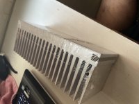
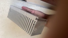
Nice chunk, Aditya, it should be a perfect match for the C
If you want good audio than you need to use raspberry pi with a dac PCM5242 or PCM5122 and use linear supply for it. And install Moode or Volumio.
I am using it as regular thing only difference in my approach is I m using a just boom amphat so this board has a Texas Chip with 192KHz / 24bit dac with a 30 + 30 class D HD amp built into it.
Advantage using a SBCis I can play any format audio and have airplay and Bluetooth along with usb Hdd support
Mr Elvee,
Based on your recommendation of Bootstrapping circuit, I did following modification to the exixting build. This is what I achieved on the simulation at 1.5V input with 35-0-35 V DC rail. Snapshot is attached.
I am attaching simulation file with the request to please check whether I am getting such a low THD at 1KHz in actuals or I am doing some mistake.
LT Spice models of transistors used in the schematic is also attached.
Thanks
Attachments
If you want good audio than you need to use raspberry pi with a dac PCM5242 or PCM5122 and use linear supply for it. And install Moode or Volumio.
I am using it as regular thing only difference in my approach is I m using a just boom amphat so this board has a Texas Chip with 192KHz / 24bit dac with a 30 + 30 class D HD amp built into it.
Advantage using a SBCis I can play any format audio and have airplay and Bluetooth along with usb Hdd support
To my experience, building a better source (DAC in my case) is a never ending experience. I realized that I spent much more time for trying to build a proper DAC unit than I listen to music, which is the fundamental cause of whole thing.
As a turning point, I decided to end this never ending turmoil last year and I bought a proper unit from China (Gustard X26 Pro). Thanks for those Chinese manufacturers, bloat priced DAC business ran by Western companies is in threat for last couple years. We can now get -122dB THD+N units with remote and volume control for very reasonable prices. Wtih their very low output impedance and digital volume control, we can even avoid preamps when directly connecting them to amplifiers.
I think that Circlophone is the ultimate amplifier for such purpose. Circlophone is a very silent amp (almost zero with 100dB speakers in my case) and you don't have to attenetuate input signal with an analog volume control if you source is quiet enough.
Last edited:
To my experience, building a better source (DAC in my case) is a never ending experience. I realized that I spent much more time for trying to build a proper DAC unit than I listen to music, which is the fundamental cause of whole thing.
As a turning point, I decided to end this never ending turmoil last year and I bought a proper unit from China (Gustard X26 Pro). Thanks for those Chinese manufacturers, bloat priced DAC business ran by Western companies is in threat for last couple years. We can now get -122dB THD+N units with remote and volume control for very reasonable prices. Wtih their very low output impedance and digital volume control, we can even avoid preamps when directly connecting them to amplifiers.
I think that Circlophone is the ultimate amplifier for such purpose. Circlophone is a very silent amp (almost zero with 100dB speakers in my case) and you don't have to attenetuate input signal with an analog volume control if you source is quiet enough.
Happy Agreed, 🙂
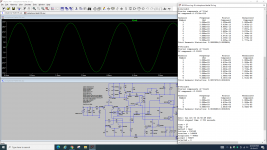
The THD predicted by LTspice is what it is, it should be taken with a pinch of salt, but I see two issues: mainly the low value of C10.Mr Elvee,
Based on your recommendation of Bootstrapping circuit, I did following modification to the exixting build. This is what I achieved on the simulation at 1.5V input with 35-0-35 V DC rail. Snapshot is attached.
I am attaching simulation file with the request to please check whether I am getting such a low THD at 1KHz in actuals or I am doing some mistake.
LT Spice models of transistors used in the schematic is also attached.
Thanks
To remain effective at VLF, the time-constant C10*R19 should be well larger than the period of the lowest frequency to process.
You currently have 270µs, but since most of the energy of an audio program is at low frequencies, you should aim at ~100ms.
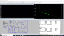
The low value of R19 is also contentious, not only for time-constant issues: a low value generates a very high bootstrap voltage (more than 70V peak), as illustrated in this screenshot:
This will stress (probably unnecessarily) a number of components including the diode, and increase the dissipation.
It might have a favourable effect on the THD figure, but this has to be balanced against the possible drawbacks.
I suggest you use more reasonable values for the bootstrap passives, but feel free to experiment, in sim and reality
Attachments
Mr Elvee,
Thank you for explaining the theory behind the circuit. I was not well acquainted with it in detail.
Katiyar
Thank you for explaining the theory behind the circuit. I was not well acquainted with it in detail.
Katiyar
Mr Elvee,
I want to give you my practical feedback for your designed MOSFET Circlophone schematic after two months of continuous use:
My MOSFET build is powered on since August 7, 2021 except for few hours outage on account of incorporation of Bootstrapped circuit suggested by you. Parameters e.g Offset voltage, Quiscent current and case temperatures are maintained despite variations in Mains voltage and inadequate cooling due to tight enclosure spacing.
This amplifier build is Rock solid stable under all conditions even with normal temperatures with out airconditioner.
Details of my build are at Post # 1988.
Thank you very much for the wonderful invention.
Thanks for your feedback: positive or negative, it is always appreciated and useful.
Is your bootstrap mod now part of your current build, or did you just make a one-off test and revert to your initial build?
Is your bootstrap mod now part of your current build, or did you just make a one-off test and revert to your initial build?
Mr Elvee,
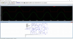
I have incorporated the Bootstrap circuit in my build. I had to choose resistor version due to non availability of BAT with me. I donot have scope with me so I could not see the waveform in actual but I did get much lower distortion in simulation.
After so many iterations I could find the attached schematic most optimum. I donot know whether thereotically and practically it will be stable at full power since I could not test it at full power but there is no stability issue at quite high lstening levels.
The Vout FFT showed wierd harmonics with bootstrap circuit which were not there previously yet there is no change in sound quality. As a designer you can tweek it further w.r.t stability issues if you could spare some time on this schematic.
Attachments
In fact, you do not really need to use a BATxx.
Any signal diode, typically 1N4148 or BAV20 will work in this role.
In theory, a schottky has ~zero recovery time, but at an audio time-scale, the 5ns or so of the 1N4148 is completely negligible.
I do not see any stability issue with your latest implementation, but the 100µF cap is a bit low, considering the resistor values.
220µ or 330µ would be preferable, but I recommend you upgrade to the diode version: it does not require a large cap, and is more efficient.
I wouldn't worry too much about the Fourier analysis results as long as you don't see an elephant in the room: sometimes reversing the order of two series components is sufficient to induce small changes, which of course have nothing to do with reality. These are just simulations quirks
- Home
- Amplifiers
- Solid State
- ♫♪ My little cheap Circlophone© ♫♪