A 150VA transformer would be sufficient. 5A/2x18V is comfortable enoughNeed input on the amps for 18 - 0 - 18 VAc transformer so that I could run it at full power stereo for both 4 and 8 ohms. I m unsure how it works for discrete amps sorry.
Thank you in advance
Mr Elvee, Is there any solution for symmetrical clipping in MOSFET C. Only positive half goes in to clipping by amount of GS voltage. Also series resistor of 470R at input increases slew rate of C. Thanks
Hi Katiyar
I wanted to know if I am building a stereo amp with 3055, how big a heatsink would I need.
Also what is maximum allowable wire length for 2N3055 if I use those transistors. And can you share the source of the heatsink you used for the BJT transistor.
I think there were two on one heatsink.
I m looking at a heat sink if am able to get it but the specs are 215 mm long and fins are round 75mm amd there is 14mm area behind the fins
Specs for heat are written as 0.5 C/w at 200mm
Is this ok for 4 TIP3055 or the specs are missing some information.
Hi Rajesh
Please check your pm
Regards
Aditya
Mr Elvee, Is there any solution for symmetrical clipping in MOSFET C. Only positive half goes in to clipping by amount of GS voltage. Also series resistor of 470R at input increases slew rate of C. Thanks
Please check your pm
Regards
Aditya
Aditya,
I only tested BJT version in prototype setup. I have working Circlophone in MOSFET version in Stereo setup which is in daily use and continuously powered on for more than a month.
I already had two separate heat sinks for output devices. These are small heat sinks 5"x5"x2" each. I know it is not sufficient for rated power but I had the limitation.
Shorter wire length from PCB to Output transistors is always better in order to minimise possible oscillations. Use shortest possible length with alleast 1 mm Sq wire.
Circlophone ideally dissipates around 160~200 ma of quiescent current per channel. Its operation is between Class A & Warm Class AB therefore a large heat sink is always better. The specs of heat sink seem OK for one channel for rated power. In this case you can use two separate heat sinks if your enclosure permits.
There is in fact a solution: the whole driver assembly can be bootstrapped to allow the maximum voltage swing.Mr Elvee, Is there any solution for symmetrical clipping in MOSFET C. Only positive half goes in to clipping by amount of GS voltage. Also series resistor of 470R at input increases slew rate of C. Thanks
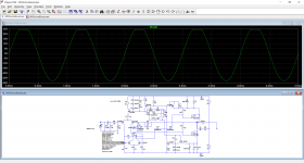
To illustrate this, here is your unmodified FET version when overdriven (there are minor transistor changes, but it's to accommodate for the native LTspice library):
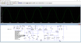
Now, here is the same circuit, also overdriven, but with the bootstrap installed:
The mods should work in reality, and the power lost in the resistor should remain <1/2W.
Can you clarify your issue with the 470R?
Attachments
The 2N3055's are essentially current-driven, meaning the wiring length is relatively unimportant (within reason).Also what is maximum allowable wire length for 2N3055 if I use those transistors. And can you share the source of the heatsink you used for the BJT transistor.
It is preferable to mount the B-E resistor directly on the transistor itself, not on the PCB, and to twist the three wires together
There is in fact a solution: the whole driver assembly can be bootstrapped to allow the maximum voltage swing.
Now, here is the same circuit, also overdriven, but with the bootstrap installed:
The mods should work in reality, and the power lost in the resistor should remain <1/2W.
Wish I know this earlier. I thought that it is a fundamental issue relating with nature of the FETs. Thanks for Elvee for quick solution and Katiyar for bringing up this. I didn't sim it yet but I hope this won't bring some other issues like degraded stability and THD.
One might object to the discontinuities introduced by the diode; they are minimal, especially with a schottky, but they are present and although they should not cause troubles thanks to the symetrical nature of the structure among other factors, they could make purists uncomfortable.
It is possible to dispense with the diode, but it requires more power, because the bootstrap becomes completely linear, and wastes power for the whole of the cycle.
In addition, the increased impedance might cause stability issues (reducing the impedance would be possible, but at the cost of even more lost power).
Here is an example anyway, for what it's worth:
Attachments

Mr Elvee, I have seen in some old MOSFET amplifier schematics where the Rail voltage of Driver stage is more than the Rail voltage of output stage. I think this is precisely due to this only.
I didn't sim it yet but I hope this won't bring some other issues like degraded stability and THD.
According to sim, THD drops from 0.005 to 0.001 with schottky and to 0.002 with resistor. Quite interesting.
Hi Katiyar,
would you be able to share your Gerber, wanted to get the PCB made?
Regards
Aditya J. Mody
Aditya,
I only tested BJT version in prototype setup. I have working Circlophone in MOSFET version in Stereo setup which is in daily use and continuously powered on for more than a month.
I already had two separate heat sinks for output devices. These are small heat sinks 5"x5"x2" each. I know it is not sufficient for rated power but I had the limitation.
Shorter wire length from PCB to Output transistors is always better in order to minimise possible oscillations. Use shortest possible length with alleast 1 mm Sq wire.
Circlophone ideally dissipates around 160~200 ma of quiescent current per channel. Its operation is between Class A & Warm Class AB therefore a large heat sink is always better. The specs of heat sink seem OK for one channel for rated power. In this case you can use two separate heat sinks if your enclosure permits.
would you be able to share your Gerber, wanted to get the PCB made?
Regards
Aditya J. Mody
Aditya, Softcopy is at post#2005 for MOSFET version. I do not have gerber for BJT version. BTW whom do you intend to get the PCB fabricated?. Pl share address of the firm.
I had got the "My Ref Rev A" PCB board done from circuitwala recently they are Indian based in Gujurat.
I found it Resonable as 3 boards cost me around 2400/- with GST.
My thought and logic was instead of going to pcbway or jlpcb and then pay more on custom duties - this vendor was decently priced and my boards were 60micron copper with silkscreen top and bottom green masking. nicely made.
they have a web interface similar to the famous PowerPCB but they are more economical.
Indian Fabricators are getting better so why look elsewhere, if we look elsewhere when will we grow...
Hi Rajesh,
I wanted the BJT file if that is possible in a softcopy, not the HexFet one.
Regards
Aditya
Aditya, Softcopy is at post#2005 for MOSFET version. I do not have gerber for BJT version. BTW whom do you intend to get the PCB fabricated?. Pl share address of the firm.
I wanted the BJT file if that is possible in a softcopy, not the HexFet one.
Regards
Aditya
@aditya, you can also take a look at Bangla H's gerber files starting from post #1793. These ones are two layer gerber files.
Interesting and encouraging, indeed, but when it comes to very low THD levels in sim, they need to be confirmed in reality.According to sim, THD drops from 0.005 to 0.001 with schottky and to 0.002 with resistor. Quite interesting.
Sims are incredibly useful to highlight possible issues and their remedies, but once you have reached the performance floor, some kind of reality-check is required because many subtler higher-order effects aren't properly modelled, or some non-linearities happen to compensate one another in the sim, but not in reality.
The opposite can be true too, but it is a rarer occurrence: something like 20% against 80%.
If you have a working MOS-circlophone, testing the bootstrap should not be difficult or intrusive: you just need to add three components, and cut one or two tracks, depending on how the existing PCB was laid out
- Home
- Amplifiers
- Solid State
- ♫♪ My little cheap Circlophone© ♫♪