Hello Terranigma,
i use Diptrace.
And it's a pleasure to share the Gerbers.
Yes, there are, not to forget, other members who inspired to make compact layout.
I have also build a MosFet based with FQP24N08 for use with only 15VAC
supply.
A bit tricky TO220 to TO247 Pins.
It isn't finished yet...but close.
i use Diptrace.
And it's a pleasure to share the Gerbers.
Yes, there are, not to forget, other members who inspired to make compact layout.
I have also build a MosFet based with FQP24N08 for use with only 15VAC
supply.
A bit tricky TO220 to TO247 Pins.
It isn't finished yet...but close.
Attachments
This clearly points to a strong, SHF (multi-GHz) pollution: C5 probably closes a small, local loop acting as an antenna. When it is not present, the input circuit is closed through lossy impedances which helps reducing the unwanted signal seen by the input transistor (and the resulting envelope rectification).Except discarding the C5 from circuit completely. That was the most significant difference that I tried. It seems like that this cap introduces more noise when it is there. Amp is not dead silent but at least I can't hear the noise when I close to the speakers.
If you have no way of turning the source of pollution off, you need drastic measures, like an EMI-resilient PCB layout, a really tight RF shield (using conductive gaskets), etc.
Certainly not an easy task.
A ferrite bead directly threaded on the base conductor of the input transistor might help, but that is far from certain.
Hello Terranigma,
i use Diptrace.
And it's a pleasure to share the Gerbers.
Yes, there are, not to forget, other members who inspired to make compact layout.
I have also build a MosFet based with FQP24N08 for use with only 15VAC
supply.
A bit tricky TO220 to TO247 Pins.
It isn't finished yet...but close.
Thank you for sharing the gerber files. Your choice of FQP24N08 is an interesting one for a small Circlophone. They specified DC SOAR and noted "suitable for audio amplifier" in datasheet. This is quite interesting for a power mosfet.
I'm thinking about a beefy Circlophone. IXYS IXTK102N30P seems a good, reasonably priced candidate for 30-40V rails. There are Linear L2 series from IXYS with more robust SOAR but they are much more pricey (about 24$/piece).
This clearly points to a strong, SHF (multi-GHz) pollution: C5 probably closes a small, local loop acting as an antenna. When it is not present, the input circuit is closed through lossy impedances which helps reducing the unwanted signal seen by the input transistor (and the resulting envelope rectification).
If you have no way of turning the source of pollution off, you need drastic measures, like an EMI-resilient PCB layout, a really tight RF shield (using conductive gaskets), etc.
Certainly not an easy task.
A ferrite bead directly threaded on the base conductor of the input transistor might help, but that is far from certain.
There is no strict EMI regulations for residential areas here thus the photo that I took today tells much more than I can say. Thank you for valuable information. I will consider them for my next project. If I didn't experience the flat dead silence of the Circlophone before, I would consider the current noise level of amp without C5 as "silent enough" but certainly not.
Another question, if I adapt the amplifier for modern 3V peak sources, is it safe to reduce 10K feedback resistor to 5.6K or lower values? As long as simulation allows for peak level before clipping, can I reduce input and feedback resistors accordingly? Is there a thumb rule for resistors?
Attachments

Last edited:
Nice environment: with a bit of ingenuity, you can probably dispense with an electricity utility subscription completely, and harvest all the energy you need from ambient fields.... some people are really spoiled: everything for free.
There might be some minor downsides, but who cares really?
The C has reasonable stability margins, and will cope without problem with moderate reductions of the closed loop gain. A 1:2 ratio should be OK, but if you need really higher reductions, you should consider alternatives, like an attenuating pad or a revision of the compensationsis it safe to reduce 10K feedback resistor to 5.6K or lower values? As long as simulation allows for peak level before clipping, can I reduce input and feedback resistors accordingly? Is there a thumb rule for resistors?
Yesterday 09:29 PM
Elvee, I have a plan about building extra two channels (4 channels total) in order to feed the amp with fully balanced sources. I can't decide which balanced analog volume control option suits best for such use: two independent C's for each channel.
I found simple solutions as shown in the attached schematic. According to the "Balanced Shunt Attenuator" solution, I can make it using a stereo potentiometer for both channels. Other one requires a matched quad channel potentiometer.
Besides these solutions, have you any other solution for such need? You always come up with some very original and simple ideas. I wonder your evil mad scientist instincts tell something about this.
Attachments

Last edited:
A bit tricky TO220 to TO247 Pins.
TO220 to TO247 heatsink adapter also available:

Besides these solutions, have you any other solution for such need?.
For now, nothing springs to my mind but I'll think about it
For now, nothing springs to my mind but I'll think about it
Other thing that I forgot to mention is that keeping output impedance as low as much possible, if it is doable without buffer when balanced source is used.
If a buffer needed (4 channels in my situation) anyhow, using my DAC's digital attenuator seems more reasonable option. The drawbacks of connecting the DAC directly to the amp are; dangerous instantaneous pops that may appear and reduced resolution at low volume levels.
Hello Peufeu,A bit tricky TO220 to TO247 Pins.
don't know if it needs that.
I have seen a pic with LU1014 doing that for Pass Amp.
As i said not finished, but the FQP was tested in a Juma F5 HA as mighty F5
with 18VDC biased to 0,5A. P-Typ: FQP27P06
The MosFet dissipates well and worked stable for any weeks many hours daily.
I have done some rework to the Terra MosFet Board ,so be careful to previous
showed, not sure about failures i have done.
Use Gerber Viewer for control. (GerberLogix)
Regards to All
Attachments

I have done some rework to the Terra MosFet Board ,so be careful to previous
showed, not sure about failures i have done.
Use Gerber Viewer for control. (GerberLogix)
Regards to All
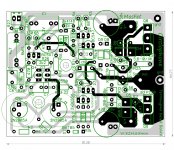
Very nice looking PCB. I couldn't see any layout errors but I can suggest one thing to consider: Can you add solderable track between vias of power ground at bottom and speaker output track at top? They seem quite thick but we can support the tracks with extra solder with no cost. I think ~3mm solderable track is enough. The long ground track that goes to the input section doesn't need that.
Thanks Terra for kind comment. I know i'm not an expert anyway.Can you add solderable track between vias of power ground at bottom and speaker output track at top?
About to do these option also in other boards i have to take the hard way to solve how many steps will work (described) as they should.
But next Time i will not find time to work on, because i move 700km away where i now live...new job, new people...new place.
Many more things to organize, you maybe now.
But i keep that in mind as to do soon as possible.
I am also curious if i can find out how to do...think with much scratching my head, sometimes with any words, not for every ones ears.
We will see. 😱 😡


 so on.
That is what i found in diptrace forum:
Just throwing this idea out there for anyone needing to unmask a complex collection of trace segments in one pass. Any and all suggestions/improvements are welcome.
p.s. Here's a more detailed procedure that should automatically place the solder mask openings in the correct location...
1) Select/highlight the trace segments that need to have the solder mask opened up over them and copy the selection to the clipboard (Ctrl + C).
2) Open a new (blank) instance of the PCB Layout editor and paste the contents of the clipboard into the new Design Area (Ctrl + V).
3) In the new PCB layout set the grid size to 3mm, select/highlight all objects (Ctrl + A), press the up-arrow key once and press the left-arrow key once. This should move all objects up 3mm and left 3mm.
4) While still working in the new PCB layout click on "File" in the Main Menu, choose "Export" in the drop-down menu and select "DXF..." in the fly-out menu to bring up the Export DXF dialog window.
5) In the Export DXF dialog window set Units: to "mm", select/highlight the layer on which the objects reside, make sure that the option [x]Use Design Origin is enabled and click on the [Export] button to bring up the Save As dialog window.
6) In the Save As dialog window enter a file name (e.g. "soldermask"), choose a convenient folder (e.g. Desktop) and click on the [Save] button.
7) Close the new instance of the PCB Layout editor without saving the new PCB file.
8) Returning to the original PCB layout, click on "File" in the Main Menu, choose "Import" in the drop-down menu and select "DXF..." in the fly-out menu to bring up the Open dialog window.
9) In the Open dialog window locate and select/highlight the new DXF file (e.g. "soldermask.dxf") and click on the [Open] button to bring up the Import DXF dialog window.
10) In the Import DXF dialog window set DXF Units: to "Millimeters", Import Mode: to "Add", Convert to: to the desired solder mask layer (choose either "Top Mask" or "Bottom Mask") and click on the [Import] button.
11) Use the 3D Preview tool to confirm that the solder mask has been opened up over the desired trace segments.
Holy cow. I will need 1 day or longer with my old braicells, but a way to try learning...oh je. 😕
Power mosfet input capacitance vs Circlophone
Elvee, I don't know this topic discussed in thread but I decided to ask anyway.
Power mosfet input capacitances varies from several 100pF's to several 10nF's. I want to ask you that is there a input capacitance limitation for mosfets when they used without drivers in C?
For instance, If I use a 7.5nF power mosfet, which aspect will be degraded most? I have read that input capacitance affects slew rate if there is not much current to drive these devices. Can you give a brief info about this subject regarding the Circlophone?
The capacitance will of course affect the dynamic performances. The input capacitance (Cgs) will play a minor role, unless it is really huge, but the one to look for is the feedback capacitance (Cgd) as it will cause the Miller effect.
It is not simple to accurately predict the effect just based on the datasheet values.
If you want to have a first estimation (crude), you can simulate the amplifier with the MOS you intend to use, but only the reality will give you a really accurate answer
BTW, I didn't have a light-bulb moment regarding your balanced volume problem (except weird ones that would only work in theory), thus your best bet is to stick with one of the conventional solutions
Last edited:
Dear Elvee,
I am not able to get BAT schottky signal diodes here in India. I am getting 3 amp schottky in the market. I am getting 1N5819 - 1A Schottky Barrier Rectifier Diode in the market. Can I use it in the circuit.
Thanks
I am not able to get BAT schottky signal diodes here in India. I am getting 3 amp schottky in the market. I am getting 1N5819 - 1A Schottky Barrier Rectifier Diode in the market. Can I use it in the circuit.
Thanks
Unfortunately, a large schottky will probably have a too low Vf.
Note that there are many small schottky's with another prefix than BAT or BAS: there are also 1Nxxxx types, one of them must be another 1N5xxx, but I don't remember exactly which one.
The HP 5082- series is another possibility, but they are expensive. They have second sources from Diodes and others.
Japanese and Korean manufacturers also make signal schottky's.
If you don't find anything, you can (very carefully) try a 1N4002 or a small Ge like AA119 or OA95.
Only attempt that on a current-limited lab supply, in case things go wrong
Dear Mr Elvee,
I want one more advice from you. I have BF469 and 2SC2621 pulled from my old discarded colour TV and new Philips BF869 transistor with me. Can I use them for VAS in place of 2N3019 which is not available easily in India. I can get few new 2N3440 transistor as well. I need your expert advice which transistor will be most suited for VAS. Thanks. Katiyar
I want one more advice from you. I have BF469 and 2SC2621 pulled from my old discarded colour TV and new Philips BF869 transistor with me. Can I use them for VAS in place of 2N3019 which is not available easily in India. I can get few new 2N3440 transistor as well. I need your expert advice which transistor will be most suited for VAS. Thanks. Katiyar
Attachments
- Home
- Amplifiers
- Solid State
- ♫♪ My little cheap Circlophone© ♫♪