PCB Layout -reg
Hi,
I am very much excited to make this nice ampifier.
Can somebody point me to the pcb layouts/files?
Thanks and regards,
sumesh
Hi,
I am very much excited to make this nice ampifier.
Can somebody point me to the pcb layouts/files?
Thanks and regards,
sumesh
Dear Sumeshak,
Please see
Building Elvee's Circlophone: Documentation, Parts, Accessories, & beginner friendly, post by pronk.
That PCB layout is good. Please contact pronk by pm for PCB files.
--gannaji
Please see
Building Elvee's Circlophone: Documentation, Parts, Accessories, & beginner friendly, post by pronk.
That PCB layout is good. Please contact pronk by pm for PCB files.
--gannaji
Thank you
Thank you sir,
I shall do so.
Regards,
Sumesh
Thank you sir,
I shall do so.
Regards,
Sumesh
Dear Sumeshak,
Please see
Building Elvee's Circlophone: Documentation, Parts, Accessories, & beginner friendly, post by pronk.
That PCB layout is good. Please contact pronk by pm for PCB files.
--gannaji
Elvee,
My build is not dead silent when inputs are open or connected to a source. I can hear a annoying HF noise when I sit close to the speakers. It is not 50hz mains hum. But when I short RCA input, it becomes dead silent even if I close to my ears to the speakers.
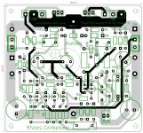
Does this behavior give you any idea regarding the source of noise? My PCB layout is here. I did not separate low level signal grounds from rail ground as you can see on PCB layout. Since noise is not there when inputs are short, does it mean that layout is ok and I have to look at somewhere else?
Mains earth is connected to the chassis but entirely isolated from amp.
My build is not dead silent when inputs are open or connected to a source. I can hear a annoying HF noise when I sit close to the speakers. It is not 50hz mains hum. But when I short RCA input, it becomes dead silent even if I close to my ears to the speakers.
Does this behavior give you any idea regarding the source of noise? My PCB layout is here. I did not separate low level signal grounds from rail ground as you can see on PCB layout. Since noise is not there when inputs are short, does it mean that layout is ok and I have to look at somewhere else?
Mains earth is connected to the chassis but entirely isolated from amp.
Circlo Board
Hello sumeshak
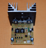
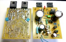
i have done a board based on project 16 showed here.
If you like you, and other please, can look in detail if all is correct done.
I have ordered a batch by pcbway any time back but not started assembling now.
🙄
Regards
Hello sumeshak
i have done a board based on project 16 showed here.
If you like you, and other please, can look in detail if all is correct done.
I have ordered a batch by pcbway any time back but not started assembling now.
🙄
Regards
Attachments
First look at the usual suspects: ground currents and ambient emi pollution.Elvee,
My build is not dead silent when inputs are open or connected to a source. I can hear a annoying HF noise when I sit close to the speakers. It is not 50hz mains hum. But when I short RCA input, it becomes dead silent even if I close to my ears to the speakers.
To test for ground issues, disconnect the source end of your input cable and short it.
Hopefully, the amp should be silent, otherwise go to section 2.
Now, press the GND shell of the (shorted) connector to the GND of the source.
Does the noise appear? If it is does, it has to do with ground currents.
Try different configurations: source powered, unpowered, completely disconnected from the mains (but maybe still connected to other audio components) etc. to try to pinpoint the origin of the offending stray current.
If the noise is present with just a shorted cable connected, the source is ambient emi pollution. Likely culprits are WiFi, Bluethooth, cellphone signal mainly, but also any other RF: Zigbee, Lora, broadcast, etc.
In this case, try to use a better cable, CM ferrites, a SMD 1nF ceramic cap directly across the input of the Circlophone.
Also try to mute every possible source of interference in your house, and reawaken them one by one to see which one could cause the problem.
Another nice looking implementation of the C; I am sure it will appeal to a number of members!Hello sumeshak
i have done a board based on project 16 showed here.
If you like you, and other please, can look in detail if all is correct done.
I have ordered a batch by pcbway any time back but not started assembling now.
🙄
Regards
First look at the usual suspects: ground currents and ambient emi pollution.
To test for ground issues, disconnect the source end of your input cable and short it.
Hopefully, the amp should be silent, otherwise go to section 2.
Now, press the GND shell of the (shorted) connector to the GND of the source.
Does the noise appear? If it is does, it has to do with ground currents.
Try different configurations: source powered, unpowered, completely disconnected from the mains (but maybe still connected to other audio components) etc. to try to pinpoint the origin of the offending stray current.
If the noise is present with just a shorted cable connected, the source is ambient emi pollution. Likely culprits are WiFi, Bluethooth, cellphone signal mainly, but also any other RF: Zigbee, Lora, broadcast, etc.
In this case, try to use a better cable, CM ferrites, a SMD 1nF ceramic cap directly across the input of the Circlophone.
Also try to mute every possible source of interference in your house, and reawaken them one by one to see which one could cause the problem.
Here is my observations:
Noise is present when using a 1.5m cable shorted at source side. Connecting it to source ground (cable is still shorted) makes it even worse (which is my current situation).
When cable is still shorted, its direction has a significant effect on noise level. When I lay down the cable at North-South direction, noise is obviously present. When I lay down on East-West direction noise level noticeably lowers but not entirely gets lost.
So, pollution seems the real culprit here. I will follow your advises.
Thank you.
Did you implement the filter R19/C5? It should be effective at eliminating RF pollution.
The shield itself of the cable might act as an antenna, and inject RF into the GND input zone. A CM ferrite could help in this case.
The shield itself of the cable might act as an antenna, and inject RF into the GND input zone. A CM ferrite could help in this case.
PCB Rev
Thank you Elvee,
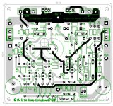
i've done a copy of a nice layout project 16 based board.
For better placement i have added pads to some capacitors.
Revisited Board.
On Terra's MosFet circlophone with Darlingtons, on my not that good self etched board, a helpful guy heightened
R25 to 10 ohm and C7 to 100n, also the FB C4 to 39p
and added a R 5,6 ohm 1W to C1 parallel if i remind correct.
Maybe that helps too?
I have later recycled it.
Later done a new board, but not connect to rails and speakers yet...
Thank you Elvee,
i've done a copy of a nice layout project 16 based board.
For better placement i have added pads to some capacitors.
Revisited Board.
On Terra's MosFet circlophone with Darlingtons, on my not that good self etched board, a helpful guy heightened
R25 to 10 ohm and C7 to 100n, also the FB C4 to 39p
and added a R 5,6 ohm 1W to C1 parallel if i remind correct.
Maybe that helps too?
I have later recycled it.
Later done a new board, but not connect to rails and speakers yet...
Attachments

Did you implement the filter R19/C5? It should be effective at eliminating RF pollution..
Yes they are present. C5 is a styroflex type.
The shield itself of the cable might act as an antenna, and inject RF into the GND input zone. A CM ferrite could help in this case.
I'll try.
As I remember, I tried small ferrite pipes at input transistor's base legs but it wasn't effective to suppress the noise. But that was for one of my other builds.
It may have to do with fields around the mains transformer.
Maybe. I'm still trying. I hope I won't need to alter my pcb layout. That was one of my concerns.
On Terra's MosFet circlophone with Darlingtons, on my not that good self etched board, a helpful guy heightened
R25 to 10 ohm and C7 to 100n, also the FB C4 to 39p
and added a R 5,6 ohm 1W to C1 parallel if i remind correct.
Maybe that helps too?
I have later recycled it.
Later done a new board, but not connect to rails and speakers yet...
Good to see that someone took a fresh look at mosfet version. I wouldn't do two layers since the board already has done on single layer many times. Home builders may prefer one of those.
If I go for a new design, I would avoid tht components as much as possible except output devices, bypass caps and sockets and maybe other transistors. When you do own pcb's at home, drilling is the real pain besides etching.
I think such thing is missing on Circlophone side: Compact, multilayer fabricated PCB with full of SMD components (except those components above).
Btw, I tested mosfet (hexfet actually) version with 50V supply with no problem. But it was with keantoken input LTP buffer that contains extra two transistors at input. And compensation scheme was different. With combination of 50V rails and >200mA bias, heat becomes something to consider. So I postponed that project for making a good case with proper heatsinks. Heat dissipation wasn't at Class-A level but it wasn't at regular Circlophone level either.
Attachments
Last edited:
That looks impossible: it would completely disable the whole amplifier.and added a R 5,6 ohm 1W to C1 parallel if i remind correct.
Maybe that helps too?
I don't add this 5,6 ohm R, i don't trust memory....
To Terranigma:
I have done double sided that i can do fatter traces and it's cheap from board house.
To Terranigma:
I have done double sided that i can do fatter traces and it's cheap from board house.
I have done double sided that i can do fatter traces and it's cheap from board house.
You're right. I doesn't make sense make pcb's at home when you can order them with quantities for cheap. Your layout is better.
But you have done a nice compact layout first. 🙂
That gives initial inspiration to clone it in 2 layer.
I am only can catch ideas and try own way to do...like
Have to learn a lot more things....
That gives initial inspiration to clone it in 2 layer.
I am only can catch ideas and try own way to do...like
Have to learn a lot more things....
Did you implement the filter R19/C5? It should be effective at eliminating RF pollution.
The shield itself of the cable might act as an antenna, and inject RF into the GND input zone. A CM ferrite could help in this case.
Ferrite cores, different ground schemes including lifting small signal ground with a 10 ohms resistor and different C5 values didn't help. Except discarding the C5 from circuit completely. That was the most significant difference that I tried. It seems like that this cap introduces more noise when it is there. Amp is not dead silent but at least I can't hear the noise when I close to the speakers.
But you have done a nice compact layout first. 🙂
That gives initial inspiration to clone it in 2 layer.
I am only can catch ideas and try own way to do...like
Have to learn a lot more things....
That layout was also based on some other member's (Powerflux I guess) design. I heavily modified and adapted Darlington/Mosfet. Can you share pcb project files of both versions? Which program do you use?
- Home
- Amplifiers
- Solid State
- ♫♪ My little cheap Circlophone© ♫♪