I would advise against the 2N3440: it is an early type of HV transistor, and it is slow, with highish capacitances.
The C will probably manage to work with it, but the dynamic performances won't be at their best.
The 2SC2621 looks practically perfect, but the 50MHz transition frequency is a bit on the low side.
The BF469/869 are almost too good: they have a very low Ccb, which could lead to instabilities because this Ccb is used for self-compensation.
If you supplement it with an external 4.7pF, they should deliver a top performance
BF469 was an excellent transistor (for low capacitance) from the golden days of discrete analog, unfortunately discontinued, it deserves to be used 😀
The 2SC2621 looks practically perfect, but the 50MHz transition frequency is a bit on the low side.
I realized later that datasheet specifications of Ft varies by collector current (Ic). I regularly see that Ft specification made at 100mA and some times I see at 10mA. I guess Circlophone builders may consider 10mA specification or its Ft at 10mA for more technically speaking, right?
For instance I sent you a sample of 2N1893, then your measurements show that it was almost spot on:
Elvee said:2N1893 Thomson/Silec:
Ft, measured @Ic=50mA, Vce=7V, F=30MHz: 126MHz
Collector capacitance @Vce=2.5V: 10.3pF
Die volume, measured by adiabatic thermal impact, reference 2N3019=100%: 100%
No detectable spread between the two samples
But I realized that measurement was made at 50mA. Then I requested another measurement at 10mA then you measured it as 75MHz:
Elvee said:Hi Terraterranigma said:Elvee said:I tested the 2N1893 at 10mA, 20MHz, the Ft in these conditions is 75MHz.
Hello Elvee,
Can you measure a standard 2n3019 in same conditions please? I wonder how they differ in same conditions.
Thanks.
Under those conditions, I measure 105MHz for a 2N3019 Motorola (Vce=5V)
Btw, this the one that use with my daily Circlophone:
Elvee said:2N5858 Transitron:
Ft, measured @Ic=10mA, Vce=10V, F=100MHz: 500MHz
Collector capacitance @Vce=2.5V: 11.3pF
Die volume, measured by adiabatic thermal impact, reference 2N3019=100%: 100%
I want to bring the output transistors ranking methods to discussion again.
I just checked these two known transistors datasheet but couldn't figure out the ranking difference. I actually found 2N3773 is more robust despite it is ranked as 150W (vs 200W 21194). 3773's Hfe curve is not linear like a ruler but it doesn't look poor either. Actually 2N3773 has much more gain at 0-3A range. I suspect that you consider the 2N3773 as a 200kHz device.
Elvee, can you explain your ranking method please? Can we apply same methods to mosfets?
2N3773: 0.26
Elvee said:MJ(L)21194: 1.6
I just checked these two known transistors datasheet but couldn't figure out the ranking difference. I actually found 2N3773 is more robust despite it is ranked as 150W (vs 200W 21194). 3773's Hfe curve is not linear like a ruler but it doesn't look poor either. Actually 2N3773 has much more gain at 0-3A range. I suspect that you consider the 2N3773 as a 200kHz device.
Elvee, can you explain your ranking method please? Can we apply same methods to mosfets?
Yes, they operate at around 10mAI realized later that datasheet specifications of Ft varies by collector current (Ic). I regularly see that Ft specification made at 100mA and some times I see at 10mA. I guess Circlophone builders may consider 10mA specification or its Ft at 10mA for more technically speaking, right?
Pretty much idealBtw, this the one that use with my daily Circlophone:
Originally Posted by Elvee
2N5858 Transitron:
Ft, measured @Ic=10mA, Vce=10V, F=100MHz: 500MHz
Collector capacitance @Vce=2.5V: 11.3pF
Die volume, measured by adiabatic thermal impact, reference 2N3019=100%: 100%
IIRC, the formula must be something like: Ft*Hfe(lo)/Hfe(hi)Elvee, can you explain your ranking method please? Can we apply same methods to mosfets?
Plugging in the published values for 2N3773 gives 0.2*23/155=0.03, so there might be another subtlety or correction, or I used the Ft of the currently available production, having a Ft of 0.8 or 2Mhz.
For Mosfets, there is no Ft equivalent, and you should look for the constancy of transconductance vs. drain current
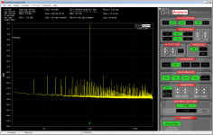
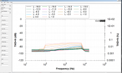
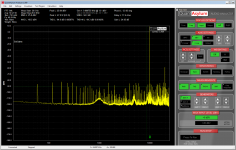
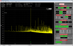
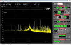
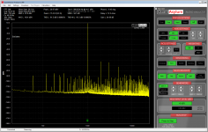
Not sure if anybody needs to know this, but here are my measurements of my circlo build with QA401 audio analyzer.
Rails were 42V. Load 8.8 Ohm.
Thd from 0.0019% at 1W to 0.035 at 50W.
Very linear with frequency.
Edit: interesting thing - in my un-experienced eyes, it seems that circlophone measured slightly better than Elvee's active current dump amp. Will re-test, and publish results.
Rails were 42V. Load 8.8 Ohm.
Thd from 0.0019% at 1W to 0.035 at 50W.
Very linear with frequency.
Edit: interesting thing - in my un-experienced eyes, it seems that circlophone measured slightly better than Elvee's active current dump amp. Will re-test, and publish results.
Attachments
Last edited:
Thanks for sharing your results with the community. High quality, reliable measurements are always welcome and useful, and you seem to search for perfection in this field, just as you do in your builds (which are masterpieces!).
Dear Mr Elvee,
What type of capacitor C4 across R17 should I use?. Ceramic type may cause noise as it may act as a condenser microphone. Mica /Slvered Mica is very expensive and not available easily available in India. Could you please advise on this issue.
What type of capacitor C4 across R17 should I use?. Ceramic type may cause noise as it may act as a condenser microphone. Mica /Slvered Mica is very expensive and not available easily available in India. Could you please advise on this issue.
COG ceramic is very little microphonic, and C4 has no DC voltage across it.
Otherwise, PS, PP and other quality plastics are also OK
Otherwise, PS, PP and other quality plastics are also OK
Hello Elvee,
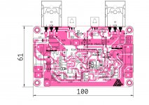
Here is another "done to Death" layout for vanilla version for your amplifier.
Can you tell me if 2sc4793 is suitable for Q5/Q6 or 2sa1837 for Q9/Q11? Sorry if this already answered before, i only had speed-read the long thread.
In layout, I have provided option for TO-220 pads for Q5/6.
regards
prasi
Attachments
Last edited:
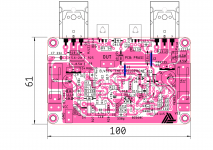
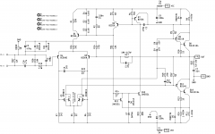
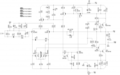
Slightly revised and with component values.
I liked your layout. If this one appeared on this thread earlier, I would not make my own PCB which looks similar to yours.
My suggestions are:
It seems you omitted optional 10nF cap (C11 on original schematic). This cap is needed when higher speed output transistors used.
You can preserve more space around Q5 and Q6 because these are running relatively hot. They must be apart from C8 for same reason.
Dear Prasi.
What is the reason for putting R Ground as this will float above 0V and is als not as per tested original schematic designed by Mr Elvee. Which TO 200 transistors you intend to use for VAS. C10 seem to be Metallised Polyster Capacitor could you please send the name of the seller. Thanks
What is the reason for putting R Ground as this will float above 0V and is als not as per tested original schematic designed by Mr Elvee. Which TO 200 transistors you intend to use for VAS. C10 seem to be Metallised Polyster Capacitor could you please send the name of the seller. Thanks
Hello Katiyar,
Rgnd is just as a ground lift option for experimentation, if not required, can be replaced with link.
TO-220 replacements are given somewhere in build thread.. 2SC5171 i think.
4.7u in 7.2mm x 7.2 mm case is made by wima and kemet.. https://www.mouser.in/Passive-Compo...Z1yznbzsZ1yznbzqZ1z0vn48Z1yzuws0&Ns=Pricing|0
but one can easily fit a nice bipolar panasonic SU or nichicon muse in its place.
I liked your layout. If this one appeared on this thread earlier, I would not make my own PCB which looks similar to yours.
My suggestions are:
It seems you omitted optional 10nF cap (C11 on original schematic). This cap is needed when higher speed output transistors used.
You can preserve more space around Q5 and Q6 because these are running relatively hot. They must be apart from C8 for same reason.
Thank you terranigma, for your kind words.
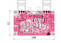
With a little bit of move there and here, I have managed to leave some space around Q5/Q6. I plan to use 33VDC, so for that, do I need to sink Q5/6, I see that in original Elvee's build , I could not see heatsinking. correct me if I am mistaken.
regards
prasi
Attachments
Thank you terranigma, for your kind words.
With a little bit of move there and here, I have managed to leave some space around Q5/Q6. I plan to use 33VDC, so for that, do I need to sink Q5/6, I see that in original Elvee's build , I could not see heatsinking. correct me if I am mistaken.
regards
prasi
This is much better. I think you will omit C11 (10nF) anyway.
When I first built Circlophone with 33V rails (like yours) I noticed that they are too hot to touch. Even though Elvee said that it is safe (because they're running in Class A) I felt more comfortable with heatsinks. Also heatsinks makes the board looks better. In short, they are safe without heatsink but you can attach a heatsink if you prefer like mine.
Elvee's post regarding this issue is at #383
Edit: I see that you fit C11. So avoid that part from my post above.
Last edited:
A very lovable design: it has everything going for it: neat, compact, sensible, well thought outWith a little bit of move there and here, I have managed to leave some space around Q5/Q6. I plan to use 33VDC, so for that, do I need to sink Q5/6, I see that in original Elvee's build , I could not see heatsinking. correct me if I am mistaken.

For moderate supply voltages (up to +/-45V), no heatsink is necessary (it also depends on the case: a TO126 or 202 can dissipate more that a TO5)
- Home
- Amplifiers
- Solid State
- ♫♪ My little cheap Circlophone© ♫♪