Hi Elvee,
Is it possible to bridge two Circlophones to get more power?
Thanks,
Bibin
Bibin hi!
Normally we use bridge connectivity when the supply is low like the 12 volt car/boat battery. This is why the high power car amps all have an invertor that push the voltage supply to whatever your need may be. There should be no reason not to do it as far as I know.🙂😱
Thank you Prashant (Prasi). Those LED are optional and for D4, D5 I used SR504 - Schottky Diodes 5A 40V .
Thanks,
Bibin
OT here, but need to clarify one thing.
Dear Bibin,
I prefer to be addressed Prasi here (if you read my posts and my profile).
I do not know whats with Prashant (Prasi) that you used twice while answering my post😕.
If you need more clarification on my identity, you can always contact by PM🙂 or by email.
reg
Prasi
Hi Prashant (Prasi),
I have used KSC2690A instead of 2N3019. Attaching an image of my completed Circlophone.
An externally hosted image should be here but it was not working when we last tested it.
Thanks,
Bibin
Bibin,
Beautitul work
 😎
😎Sa muli,
Albert
[formerly Abetir]
hope that comes thru attachmentCan you post the 3-way speaker model you used for simulation?
this is static model! no back emf and further simplified : no vent
Attachments
Bibin hi!
Normally we use bridge connectivity when the supply is low like the 12 volt car/boat battery. This is why the high power car amps all have an invertor that push the voltage supply to whatever your need may be. There should be no reason not to do it as far as I know.🙂😱
Thank you for the quick update and clarification.
Bibin,
Beautitul work
Sa muli,
Albert
[formerly Abetir]
Thank you Albert for the comment.
Thanks, I will investigate and report the results.hope that comes thru attachment
this is static model! no back emf and further simplified : no vent
Just like the majority of modern amplifiers, the C. can be bridged: it has both inverting and non-inverting inputs, the rest is a question of resistors and topological optimization.Hi Elvee,
Is it possible to bridge two Circlophones to get more power?
Thanks,
Bibin
I will try to offer something effective and sensible.
Note that the C. can work with voltages as low as 10~12V (must be somewhere in the thread, I don't know exactly where), but as there are no miracles or free lunches, the output power will be limited by Joule's law.
For a modest yet significant upgrade without the complications of a full-feature regulated converter, you can always turn to Boostor, a simplistic unregulated charge-pump converter:
http://www.diyaudio.com/forums/power-supplies/212945-boostor-ideal-companion-circlophone-move.html
Here is an example of bridging; it does not particularly shine for its originality, but at least it should work without problems:Hi Elvee,
Is it possible to bridge two Circlophones to get more power?
Thanks,
Bibin
Attachments

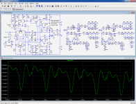
Here is the test using your 3 way model, first the "normal" way. I have paralleled two networks to push the amplifier to its limits in order to show possible problems:Setting the Amplitude and frequency variable in sine gen of LTSpice to {inlvl} and {fre} resp. for ex. then Spice command .step param inlvl 0.01 1.1 0.05 and .step param fre 100 5000 500 give one logfile with all of these combinations for .four {fre} V(OUT)
The basic Circlophone behaves quite good but one can observe there is still crossover distortion left . One should plot the 3rd and 5th harmonic. However another very popular DIY amp does not so well - i don't mention which one. Preferably the load should be a Spice model of a 3 way passive speaker. What happens when a signal is fed in the output via the voice coil model -inductance and resistor in series. Hum...it attenuates 10 volts sine gen to just 0.8 Volts at output and oscillates. Provided the simulation is about correct then Circlophone cannot cope with the emf signal of a speaker. Try yourself - don't forget input must be grounded
The trace shows the distortion residue extracted by subtraction from Vs.
Most of the THD is pretty mundane, mainly 3rd and fifth, and a small Xover residue-like is also visible. It is caused by the high current flowing through the 2N3055's causing an accumulation of charge carriers that aren't evacuated perfectly, in spite of the circlo-engine. The engine has a limited loop gain and manages to reduce the artifacts without eliminating them completely.
We have to keep in mind that these are extreme stress condition and that the THD in these conditions is 0.002%, of which a very small fraction only is due to these artifacts: well below the ppm level.
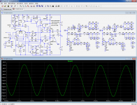
Now, let's see what happens in the conditions you described: here, the output is driven from an external 22V sine source (10% higher than the supply rails) through your doubled model network (which is not particularly gentle, as it drops to 3Ω at some frequencies).
V(Nout) is the residue present at the output now acting as a virtual ground: it shows nothing abnormal, just a very low and slightly non-linear impedance, something to be expected from a decent amplifier driven well beyond its limits.
No sign of latchup or similar pathological behavior.
These are sims of course, but the actual tests I made and the experience of circlophone builders seem to confirm the good behavior of this amplifier, even under harsh conditions
Attachments
Just like the majority of modern amplifiers, the C. can be bridged: it has both inverting and non-inverting inputs, the rest is a question of resistors and topological optimization.
I will try to offer something effective and sensible.
Note that the C. can work with voltages as low as 10~12V (must be somewhere in the thread, I don't know exactly where), but as there are no miracles or free lunches, the output power will be limited by Joule's law.
For a modest yet significant upgrade without the complications of a full-feature regulated converter, you can always turn to Boostor, a simplistic unregulated charge-pump converter:
http://www.diyaudio.com/forums/power-supplies/212945-boostor-ideal-companion-circlophone-move.html
Here is an example of bridging; it does not particularly shine for its originality, but at least it should work without problems:
Thanks a lot Elvee, that was so quick. Actually one of my friend asked me about this possibility. I will share this with him.
Thanks,
Bibin
For maniac detail nitpickers, R42 should preferably be increased to 510 ohm, but that's really icing on the cake.
In fact, it could probably be increased even more, as there is some gain stability margin, but the benefits would be quite minor, if any
In fact, it could probably be increased even more, as there is some gain stability margin, but the benefits would be quite minor, if any
Current drive
Sir, Elves, I refer to your post #1635.
First off, my profound apologies for this much-delayed response. A series of personal upsets/upheavals, though not serious per se, had kept me away from the hobby circuit; only now am I able to try and pick up the lost threads. Kindly accept my sincere gratitude for the current drive mod to the Circlophone that you had presented. You have no idea how helpful that is going to be.
You are right in that the current breed of speakers are designed for high powered voltage drive, though the amp=speaker relationship is far from ideal. But a low power current drive amp makes a wonderful combo with a good full range driver. A better bet would be to split the LF somewhere below 500 Hz, and use an active 2-way system (I use minidsp for its sheer convenience factor), which, IMHO, can easily beat a SET amp/full-range combo if you are attempting to evoke realism.
Where does the Circlophone ( my favourite amp....in a long time!) come into this formula? I fell in love with the Circlophone when current drive was not in my agenda. Now, with your kind help, I shall be able to compare side-by-side both voltage drive and current drive, using the same drivers. For such comparisons, my practice is to use limited-range (no 20 Hz to 20 kHz stuff) single and group vocal live recordings and listen and listen, looking for the closest approach to the original.
Your gracious help will be of immense value to me -- soon, I fervently hope and pray! Thank you, sir, once again! Current drive or no current drive, you can be proud that the Circlophone is one great amp topology!
Current drive-R22
I shall be much obliged if you could offer some guidance as to how to select the current sense resistor (R22) in relation to the speaker impedance - perhaps a rule-of-thumb formula?
Thanks in advance, Sir.
I shall be much obliged if you could offer some guidance as to how to select the current sense resistor (R22) in relation to the speaker impedance - perhaps a rule-of-thumb formula?
Thanks in advance, Sir.
Thread Compilation
I am re-joining after a long time, and that has brought in its own difficulties, the most tedious being leafing through the page after page of posts.
How helpful it would be if somebody could come up with a program for compiling all the posts (or, say, Pages 1 to xx) into a large text/doc file, with attachments etc. Or, has it been done already?
How helpful it would be if somebody could come up with a program for compiling all the posts (or, say, Pages 1 to xx) into a large text/doc file, with attachments etc. Or, has it been done already?
Diyaudio is designed for 90's computers on dial-up, so you only get 10 posts per page. However, if you click thread tools and choose enhanced print view, you can see all posts at once. This, however, costs money.
I shall be much obliged if you could offer some guidance as to how to select the current sense resistor (R22) in relation to the speaker impedance - perhaps a rule-of-thumb formula?
Thanks in advance, Sir.
A builders thread exist's perhaps you may find here all the help that you needed.😉
http://www.diyaudio.com/forums/soli...tion-parts-accessories-beginner-friendly.html
Regards,
Albert
The ratio of Zload to R22 should reflect the gain of the amplifier (~22 in this case)I shall be much obliged if you could offer some guidance as to how to select the current sense resistor (R22) in relation to the speaker impedance - perhaps a rule-of-thumb formula?
Thanks in advance, Sir.
- Home
- Amplifiers
- Solid State
- ♫♪ My little cheap Circlophone© ♫♪