A capacitor placed directly across the rails will have little effect, positive or negative, it is thus relatively benign and safe to try.
A capacitor between the diodes nodes will act as an AC short between these nodes, ie. it will attempt to equalize the dynamic voltages present, but in normal operation, these voltages are different, and need to be different.
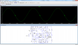
This means that the capacitor will interfere with the operation of the non-switching engine, and will seriously upset the amplifier: see for example the effect of a 100µF capacitor (C4) @1kHz.
At higher frequencies, the effect would be even nastier.
If ripple is present in the supplies, it will interact with the capacitor and add other unpleasant effects.
In summary: not recommended
A capacitor between the diodes nodes will act as an AC short between these nodes, ie. it will attempt to equalize the dynamic voltages present, but in normal operation, these voltages are different, and need to be different.
This means that the capacitor will interfere with the operation of the non-switching engine, and will seriously upset the amplifier: see for example the effect of a 100µF capacitor (C4) @1kHz.
At higher frequencies, the effect would be even nastier.
If ripple is present in the supplies, it will interact with the capacitor and add other unpleasant effects.
In summary: not recommended
Attachments
It would also upset the bias network by injecting PSU noise into the bias loop.
I suppose you could always try it just to see what it sounds like, but you would need to choose non-destructive values.
I suppose you could always try it just to see what it sounds like, but you would need to choose non-destructive values.
Thanks for the help.
So, actually safe to put a 250v 2u~5u polyester or electrolytic cap at the point where the DC umbilical cable joins the amplifier board. Now that's a bit old fashioned. The success on that depends on the resistance of the cable versus the load of the cap (together, that's a noise filter). The cables have a lot of variances (different builders, gauges and lengths) and very little loss.
The suggested cap range is for ordinary amplifiers; however, Circlophone's apparent harmonic signature is at double the frequency (half the cap value range), which is then 1u~2u2.
The lighter capacitive load also drops the effectiveness of the filter, which wasn't for much anyway, because the proportion was reliant on the cable loss (not much).
I suppose that Elvee is right. That's because half the effectiveness on that version of the filter is going to be close to nothing whatsoever. Par for the course to help normal amplifiers slightly, did not apply to the Circlophone. Even so, with the cost approximately 6 cents, I do still wonder if one might get that much value out of a very slight filter.
Inverted JFET Circlophone,
With reference to post number 331 of this threat, this is final version of the “inverted JFET Circlophone”.
Real life implementation of the attached schematic is shown in the picture.
The design is fully tested and approved by the designer of the original Circlophone, Elvee.
Highlights of this version:
Scalable outputpower, rails up to 50V
JFET input, (virtual) absence of gate/base modulation
Improved step response of the CFP configuration
Reduced phase splitter dissipation
Original Circlophone features:
No (very low…) cross-over distortion, semi class A
No need for thermal tracking the output devices
Idle current 200 mA, Gain : 28 dB
Hi,
Today my friend told about this project.First i want to say congratulations and try this nice project.How can i buy this board and matched parts?
Thank you
Hi
I would also like to build this amp. Would be really nice to know where to get the boards and maybe even some matched parts if available.
Kind Regards
Phil
I would also like to build this amp. Would be really nice to know where to get the boards and maybe even some matched parts if available.
Kind Regards
Phil
I you are interested in the "classic" Circlophone, there is a dedicated build thread:
http://www.diyaudio.com/forums/soli...ner-friendly.html?highlight=circlophone+build
For the inverted Circlophone, look here:
http://www.diyaudio.com/forums/soli...lders-thread.html?highlight=circlophone+build
http://www.diyaudio.com/forums/soli...ner-friendly.html?highlight=circlophone+build
For the inverted Circlophone, look here:
http://www.diyaudio.com/forums/soli...lders-thread.html?highlight=circlophone+build
Dear Philipp23,
Write a message to storeadmin@diyaudiocart.com. They are an Indian company, http://www.diyaudiocart.com/ and they can supply PCBs as well as Parts kit for this amp as per their private message to me.
--gannaji.
Write a message to storeadmin@diyaudiocart.com. They are an Indian company, http://www.diyaudiocart.com/ and they can supply PCBs as well as Parts kit for this amp as per their private message to me.
--gannaji.
subscribed!, well a little too late (by nearly 6 years!), but better late than never!
thanks for your design and all the efforts with your design, Elvee!
regards
Prasi
thanks for your design and all the efforts with your design, Elvee!
regards
Prasi
Setting the Amplitude and frequency variable in sine gen of LTSpice to {inlvl} and {fre} resp. for ex. then Spice command .step param inlvl 0.01 1.1 0.05 and .step param fre 100 5000 500 give one logfile with all of these combinations for .four {fre} V(OUT)
The basic Circlophone behaves quite good but one can observe there is still crossover distortion left . One should plot the 3rd and 5th harmonic. However another very popular DIY amp does not so well - i don't mention which one. Preferably the load should be a Spice model of a 3 way passive speaker. What happens when a signal is fed in the output via the voice coil model -inductance and resistor in series. Hum...it attenuates 10 volts sine gen to just 0.8 Volts at output and oscillates. Provided the simulation is about correct then Circlophone cannot cope with the emf signal of a speaker. Try yourself - don't forget input must be grounded
The basic Circlophone behaves quite good but one can observe there is still crossover distortion left . One should plot the 3rd and 5th harmonic. However another very popular DIY amp does not so well - i don't mention which one. Preferably the load should be a Spice model of a 3 way passive speaker. What happens when a signal is fed in the output via the voice coil model -inductance and resistor in series. Hum...it attenuates 10 volts sine gen to just 0.8 Volts at output and oscillates. Provided the simulation is about correct then Circlophone cannot cope with the emf signal of a speaker. Try yourself - don't forget input must be grounded
Detecting the Xover distortion that way is tricky and ineffective; anyway, you should not look at low-order harmonics like the fifth: the Xover dist. signature are a spray of higher order harmonics, typically >9th and much higher.Setting the Amplitude and frequency variable in sine gen of LTSpice to {inlvl} and {fre} resp. for ex. then Spice command .step param inlvl 0.01 1.1 0.05 and .step param fre 100 5000 500 give one logfile with all of these combinations for .four {fre} V(OUT)
The basic Circlophone behaves quite good but one can observe there is still crossover distortion left . One should plot the 3rd and 5th harmonic.
Note that the sole presence of these harmonics does not necessarily means Xover: you also have to look at each individual phase which is extremely tedious.
A much simpler and more effective method is the subtraction method: you create an arbitrary voltage source behaving as an ideal amplifier, ie. V=gain*V(in) and you compare it to the actual output: the residue is distortions (including phase ones, which can be problematic), and Xover distortion appears very clearly as short spikes centered on zero-crossings.
Do you have the .asc of such a simulated speaker.Preferably the load should be a Spice model of a 3 way passive speaker. What happens when a signal is fed in the output via the voice coil model -inductance and resistor in series. Hum...it attenuates 10 volts sine gen to just 0.8 Volts at output and oscillates. Provided the simulation is about correct then Circlophone cannot cope with the emf signal of a speaker. Try yourself - don't forget input must be grounded
I have made various stress tests, including 100% reactive loads and 100% forcing the output from an external source (in order to measure the output impedance), but I have never seen the kind of disgraceful latchup you mention. That's somewhere in the thread, but it would take forever to find where it is.
IRL too, my prototypes have been tested with insane loads (like |0.5R|), and they always behaved correctly, but it is perfectly possible I missed something.
Some more details (like the sim) would be welcome
A much simpler and more effective method is the subtraction method: you create an arbitrary voltage source behaving as an ideal amplifier, ie. V=gain*V(in) and you compare it to the actual output: the residue is distortions (including phase ones, which can be problematic), and Xover distortion appears very clearly as short spikes centered on zero-crossings.
yes that is the scope method a 2 channel scope that allows chan I - chan II
to display but is it reliable? Possibly more reliable than simulation.
To me it is only important the harmonics spectrum vs amplitude / frequency statistics which is reported in textbooks and from "psychoacoustics" it is known that an amp's harmonics spectrum going in a logarithmic manner with power and frequency has the best possible sonic qualities - subjectively of course. The absolute values of the amplitudes of the harmonics ( up to fifth)
are reportedly not that much significant for sonic impression. Not even for professional musicians' "ears"! What matters is clearly the envelope. That is not at all surprising as perceptions of "magnitudes" vision auditive ... are "logarithmic"
anyway the Circlophone sim does quite well here impression of sonic quality and result of sim match well
Last edited:
Hi Elvee, can 2sc4793 (Cob 20pF) or ksc3503(Cob 2.6pF) be used instead of 2N3019 (Cob 12pF)?
any other parameter critical that makes 2N3019 more suitable?
any other parameter critical that makes 2N3019 more suitable?
Hi Prashant (Prasi),
I have used KSC2690A instead of 2N3019. Attaching an image of my completed Circlophone.
Thanks,
Bibin
I have used KSC2690A instead of 2N3019. Attaching an image of my completed Circlophone.
An externally hosted image should be here but it was not working when we last tested it.
Thanks,
Bibin
Both will probably work, but they are a bit marginal; you could always add a 3.3pF to the 3503.Hi Elvee, can 2sc4793 (Cob 20pF) or ksc3503(Cob 2.6pF) be used instead of 2N3019 (Cob 12pF)?
any other parameter critical that makes 2N3019 more suitable?
The 3019 has nothing particularly critical, but it has good average parameters making it suitable for this application: capacitance, Pd max, voltages, Ft correct but not high to the point of causing layout issues.
Many others are suitable, and the majority of circlophones have been built with alternatives, generally without the slightest problem
Both will probably work, but they are a bit marginal; you could always add a 3.3pF to the 3503.
The 3019 has nothing particularly critical, but it has good average parameters making it suitable for this application: capacitance, Pd max, voltages, Ft correct but not high to the point of causing layout issues.
Many others are suitable, and the majority of circlophones have been built with alternatives, generally without the slightest problem
Thank you Elvee,
The reason I asked was due to common availability of 4793 in India (dont know how) and the 3503 ( websites in India offering 3503 at delicious prices).
3019 I am afraid will have to be imported from farnell. and as Bibin posted, I might as well get a kit from him for my test. Thanks dear Bibin!
reg
Prasi
Hi Prashant (Prasi),
I have used KSC2690A instead of 2N3019. Attaching an image of my completed Circlophone.
An externally hosted image should be here but it was not working when we last tested it.
Thanks,
Bibin
Dear Bibin,
congratulations, nice build with high quality components!(for us Indians🙂). is the inductor off the PCB or there is no need for it? Also which diode you used for D5/4?
reg
Prasi
Last edited:
Dear Bibin,
congratulations, nice build with high quality components!(for us Indians🙂). is the inductor off the PCB or there is no need for it? Also which diode you used for D5/4?
reg
Prasi
Thank you Prashant (Prasi). Those LED are optional and for D4, D5 I used SR504 - Schottky Diodes 5A 40V .
Thanks,
Bibin
- Home
- Amplifiers
- Solid State
- ♫♪ My little cheap Circlophone© ♫♪