Thank you, Sir Elvee...
(I just dont know what people like me would do without your hand-holding...)
(I just dont know what people like me would do without your hand-holding...)
The Inverted J-Fet Circlophone also has its own build thread:I am aware of the builder's thread. My need was to update myself about the happenings here after a long hiatus on my part.
Thanks anyway.
http://www.diyaudio.com/forums/solid-state/294338-inverted-j-fet-circlophone-builders-thread.html
Also, that is an update.
Build threads
Daniel, on behalf of a lot of members/readers, let me thank you for the "yeoman efforts" you have taken in collating the details and posting the build threads for our beloved Elvee's signature work.
All I would wish to say (without offending anybody-- people take offence so easily on many fora!) is that you could be proud that you are doing the work of a "super admin"...
Congrats and thanks again!!
which diode
Hi,
1N 5822
SB 360
BAT 60A SMD
MBR 1045
MBR 2045 CT
MBR 1625 (PBYL 1625)
these are from my local store
which diode's suitable for D4, D5 and in the Boostor?
-------------------
Q5-Q6
i have got 2N7000, is this ok?
-------------------
and,
in dc-dc smps uses U2 = TPS2811P gate driver, can i change to IR 2111
---------------------------
Boostor or SMPS, which one?
Sorry for my english, thanks.
Attachments
Hi,
1N 5822
SB 360
BAT 60A SMD
MBR 1045
MBR 2045 CT
MBR 1625 (PBYL 1625)
these are from my local store
which diode's suitable for D4, D5 and in the Boostor?
Use the MBR2045CT (both sections paralleled)
-------------------
No, these are MOSFETs, you need BJT's.Q5-Q6
i have got 2N7000, is this ok?
-------------------
and,
in dc-dc smps uses
No ideaU2 = TPS2811P gate driver, can i change to IR 2111
---------------------------
Boostor or SMPS, which one?
Both can work, the SMPS is more sophisticated and flexible, and regulated, but it is also more complex and requires the winding of a transformer
In this variant, yes, but I don't remember whether it has been tested physically or not, so be cautious in your experiments.
If you want something that has extensively been tried and tested, prefer the "classic" circlophone
If you want something that has extensively been tried and tested, prefer the "classic" circlophone
In this variant, yes, but I don't remember whether it has been tested physically or not, so be cautious in your experiments.
If you want something that has extensively been tried and tested. . . [bit different that what you'd planned]
If my engineer to english translator (currently in alpha) is working, he just said that's gonna roast your nards and your kids are gonna look really weird if you set that thing off. Or, it might have been that he said it wasn't going to do what you expected. Progress on the automatic translator is coming along slowly. . . Meanwhile, fuses work passably and Tide smells so good in the wash.
Circlophone 90 watts @ 8 ohms
Hi All
I am thrilled to see so many followers of this amp. It makes me want to build one too but with a few basic requirements. I went through a power output chart and there are options that suit my need but I want to build an amp
which is as below :
Input impedance : 47k (tube preamps are my fav)
Sensitivity : approx 1V
Power output : approx 90 watts @ 8 ohms and whatever step up I get @ 4ohms.
A lot of people vouch for the audio quality and balance of the sound across the spectrum so I won't go into any of that. I just want the amp to be stable driving 4 ohm and 8 ohm speakers.
Which board version would be good for me ?
What voltages do I run the board at for safety and stability at 4 and 8 ohms at the power output of around 90 watts ?
Which output devices are recommended ?
What component changes will I have to do to the base design of a particular board ?
This is my first attempt at building a power amp so your valuable inputs will go a long way to help out a newbie 🙂
Thank you.
The basic Circlophone will have a somewhat degraded distortion if operated at such a high impedance level; nothing catastrophic, and some people even like the added coloration, but I don't recommend it.Input impedance : 47k (tube preamps are my fav)
Solutions include the dedicated buffer: ♫♪ My little cheap Circlophone© ♫♪
Note that any other good buffer, based on an opamp for example would also work.
Another option is the FET-input, inverted Circlophone by Piersma. He might even have some boards still available.
A darlington input C has been discussed at some point, and was tested by Daniel, but no PCB has been made for it
The feedback network can easily be calculated for thatSensitivity : approx 1V
90W is close to what a single pair of transistors can safely provide.Power output : approx 90 watts @ 8 ohms and whatever step up I get @ 4ohms.
A lot of people vouch for the audio quality and balance of the sound across the spectrum so I won't go into any of that. I just want the amp to be stable driving 4 ohm and 8 ohm speakers.
Which board version would be good for me ?
What voltages do I run the board at for safety and stability at 4 and 8 ohms at the power output of around 90 watts ?
This would also mean close to 180W@4 ohm with an ideally stiff supply, which is too much to be safe. You could get away with it on an easy speaker, but one that has severe impedance dips and become highly reactive at some frequencies will kill it , for sure.
The solution is to use a power transformer dimensionned for ~100W: no more than 150 or 200VA.
The supply voltages should be ~ +/-42V
MJ21194 or similar. I think there are now 400W transistors available, but I don't remember the N° type or manufacturer.Which output devices are recommended ?
>250W and very wide SOAR are essential anyway
Any of the published board will do, you will have to add the buffer as an external module (unless someone built it in the main PCB, of which I am not aware).What component changes will I have to do to the base design of a particular board ?
This is my first attempt at building a power amp so your valuable inputs will go a long way to help out a newbie 🙂
I recommend you have a look at the builder's thread, there are useful informations
http://www.diyaudio.com/forums/soli...ly.html?highlight=circlophone+builders+thread
http://www.diyaudio.com/forums/soli...ad.html?highlight=circlophone+builders+thread
Hi Elvee,
Thank you for your inputs. I will surely look into the amp builders thread.
If 90 watts is pushing it then, I won't get too greedy on the first build and will reduce the ask from the amp to around 60 watts @ 8 ohms to begin with.
I will keep you guys posted on my progress.
Thank you.
Thank you for your inputs. I will surely look into the amp builders thread.
If 90 watts is pushing it then, I won't get too greedy on the first build and will reduce the ask from the amp to around 60 watts @ 8 ohms to begin with.
I will keep you guys posted on my progress.
Thank you.
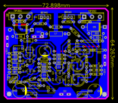
New compact PCB
Hello Folks,
Since there were no pcbs which can take KSC1845 for Q12 and Q13 (as BC546 is not suitable for voltage higher than 25) , Wanted to modify existing pcb. I had previously built circlophone using Alexmm's pcb. Hence I picked the same for my modification.
Notes :
1) 73mm X 64mm - Slightly larger than powerflux's pcb (which is smallest so far)
2) Component placement and routing is heavily influenced by Alexmm's,though I laid all the track a fresh
3) KSC1845 for Q12 and Q13
4) Drivers and outpts are on same heatsink
5) Not tested. only verified against original schematic . Will be testing it in few days
6) Exactly as per the original schematic published by Elvee
7) All resistor are sleeping position 😛 except R8,R11 and R24 which may needs to be installed vertically .
8) No C11, which is optional
Comments and criticisms are most welcome
Regards
Goutham
Attachments
The final version of the "classic" Circlophone remains that of the first message.
Many other variants have been proposed, by myself and other members, to address specific applications or use particular components, but the plain old C is still current and up to date.
You can find more details in the thread initiated by Daniel: Builder's information for the Circlophone
Many other variants have been proposed, by myself and other members, to address specific applications or use particular components, but the plain old C is still current and up to date.
You can find more details in the thread initiated by Daniel: Builder's information for the Circlophone
Thanks Mr Elvee for the response. I intend to make amplifier with your original schematics as proposed in the thread "My little cheap Circlophone".
Mr Elvee, Can I use BF469 (video transistor) with collector capacitance of 2pf in place of Q5 & Q6 (2n3019) transistors. I have taken out these transistors from my old colour TV video stage. Also can I use MJE340 in place of Q5 & Q6.
Thanks
Katiyar
Thanks
Katiyar
You can, but depending on other components, the capacitance might be too low.Mr Elvee, Can I use BF469 (video transistor) with collector capacitance of 2pf in place of Q5 & Q6 (2n3019) transistors.
In case it is, simply add a 3.3p cap between B and C
In principle, yes, but there are many sources having significantly different capacitances and Ft's, which could lead to instabilities.Also can I use MJE340 in place of Q5 & Q6.
You can make tests: instabilities when they occur remain weak and harmless
- Home
- Amplifiers
- Solid State
- ♫♪ My little cheap Circlophone© ♫♪