Power schematic? needs checked
Sorry for the late response. Electronic drawing takes a long, long time, and I was so distracted by it that I mistakenly exchanged my tea for hummingbird food, and have quite the sugar buzz. Anyway. . .
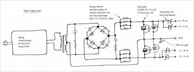
So what part of this (attachment) needs changed?
Sorry for the late response. Electronic drawing takes a long, long time, and I was so distracted by it that I mistakenly exchanged my tea for hummingbird food, and have quite the sugar buzz. Anyway. . .
So what part of this (attachment) needs changed?
Attachments
I see no need for two separate rectifier bridgesSo what part of this (attachment) needs changed?
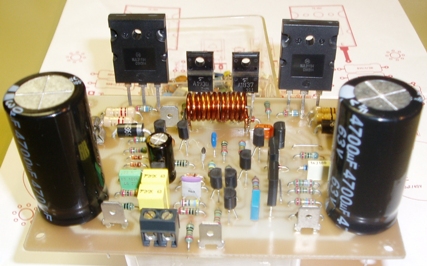
I actually like Terranigma and Piersma boards, since those are state of the art and fanless. They run the new CFP Circlophone edition. Terranigma's board is 5.7cm x 7.5cm (about 2.25 x 3 inches), has offset trim and has anti-heat-pooling design for cool running. It is a miniature marvel and the small size might be nicely cost effective for a group buy. Piersma's board is an update to Alex's and puts drivers and outputs onto one heatsink, which is the most convenient.
I have to notice that my version is a highly modified version of Powerflux that resulting my point of view. It's main disadvantage is required extra driver heatsinks. I thought it was the best compromise for keeping tracks short as much as possible and respecting that "compact" size idea.
But if you want to do something "for your own", you can screw driver transistors to the main heatsink just bottom of those screw holes if they have drilled much wider. If you loosely solder drivers to bottom of pcb using approx. 1cm wires, you can adjust place of transistors easily. If you trim driver transistor's legs good enough, track length wouldn't be a case that much.
Last edited:
I trust these clarify things a bit.
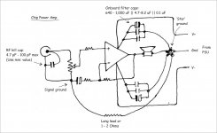
As for my take on the Circlophone PSU, I would like to do something similar, making the onboard cap perhaps 330 uF || 6.8 uF || 0.1 uF.
The input signal ground PCB trace would be cut and wired separately to the 'star' ground. In my experience with other amps, that lowers the ripple/noise threshold very much.
Happy experimenting!
Attachments
Prof,
Yes, that's much different. That thing is VDM, virtual dual mono. I did one with regs last year, and it was difficult to ground. Your solution is less expensive and much easier.
THANK YOOOOOOOO!!!!!
Circlophone is capable of a lot more power than a chip amp.
The problem with 50,000uF AND a more powerful amplifier--that is much like operating a high current device from only one little solar panel while also charging a huge marine battery. The increased workload of that much capacitance might not be as helpful as intended, because you can get "noised" instead of charged. The current dumper resistors are a further disadvantage since they can cheapen any transformer; and their presence means either not enough transformer or too much capacitance or both.
Since a charging cap is an open door to noise while it charges, I suggest a bit more concentration on keeping the caps full at the highest possible speed instead of charging as much capacitance as possible. These practicalities need a better balance.
Howabout dualie Fairchild Stealth charging lesser capacitance far out faster, staying fully charged even during playback and without using current dumper resistors at all?
Last edited:
CFP lay-out file
I will publish the files in a few weeks time from now, some PCB errors/changes need to be done to the CFP lay-out file. After the changes are made i have to test the new board. Check out this threat.
best regards,
Piersma
I will publish the files in a few weeks time from now, some PCB errors/changes need to be done to the CFP lay-out file. After the changes are made i have to test the new board. Check out this threat.
best regards,
Piersma
@Dan:
While sharing your anxieties, let me say that here we need a PSU design Guru (I am NOT one!) to lead us forward with certainties. However, let me share some of my experiences. (Somebody please correct me if I in the process dole out incorrect information...)
I had safely (and with practical improvement in performance) employed 5 x 6,800 uF per rail with a 100 W RMS discrete amp long back, using the same transformer (E-I core; not toroid) that was suggested by the designer for use with about 5,000 uF. Practically the peak STEADY-STATE currents will be more or less the same for caps in the range from say, 5,000 to 50,000 uF. But the picture is a lot different in the initial few milliseconds, and with a truly heavy-duty transformer and thick wiring, the first inrush current peak can be destructive indeed. What I did then was to use a surge limiter of about an Ohm plus, which would be shorted out by relay contacts after a delay of a couple of seconds. With the cap bank, the reduction in ripple and the overall "reserve" of power for actual musical transients was easily verifiable by casual listening. The trick here I think is to use rectifier diodes that are rated for much higher peak currents than normal; no need to go in for any fast switchers. I have heard of the Fairchild Stealth devices, but have had no experience with them.
I agree that the charging peaks have a very short duration with large cap banks, and are theoretically a good noise source. But with enough snubbering and some care, there wont be any audible or measurable artefacts. Surely in the interests of keeping ripple low and limiting the inrush current, a better solution I think would be an inductive input filter, the surge resistor being replaced by a suitable inductor before the cap bank. In a separate PSU box as here, I think we should have space for a couple of inductors, and I guess it ought to be a far better solution, viewed from all angles. Please also bear in mind that smaller caps have higher ripple ratings and lower ESRs, and so it is better to have a bank of lower value caps in parallel. Often, this will be a cheaper solution too.
Overall I guess the cap bank should prove to be an excellent performance enhancing trick with the Circlophone too, if your aim is to listen to real world music (sorry, I am NOT speaking of loud metal/hard rock fans!) and not measurements with a signal generator. That has been my experience with a series of amps of varying output powers ranging to a maximum of 120 W RMS, and as my cap bank (which peaked at 64,000 uF/per rail at one time!) was in a separate pluggable cabinet, it was easy to make comparisons.
Let us in the meantime pause for the guidance of more knowledgeable designers.
I will publish the files in a few weeks time from now, some PCB errors/changes need to be done to the CFP lay-out file. After the changes are made i have to test the new board. Check out this threat.
best regards,
Piersma
Thank you Piersma,
 it's a good thing I still had those glossy sticker paperback very efficient for use on laserjet toner-transfer.
....standing by....😀
BTW I can't find 2N3019 in my place but I found 2N2222A TO-18 metal can package, will this also work in the circuit? The datasheets do not match, if I have read it correctly, VAS trannie should have at least 800ma collector current, 2N2222A meets this requirement.

Regards!
I wish I knew how much you'd need to cut the amplifier's dc operating voltage in order to avoid exhausting the power dissipation tolerance of a 2N2222A used for VAS. ST's datasheet says collector voltage max 40vdc, meaning maximum 20v+20v rails. I totally guess that it looks good for a ~15 watt or less Circlophone, but I do not know for sure.
The 2N3019 has higher tolerances.
Do you have any of these?:
2SC3421, 2SC5171, 2N5858 2N3498, 2N3499, 2N3500, 2N3501, Panasonic DSC7102, NXP's BCP56, Philips grey case BD139, Philips BC639, authentic Hitachi 2SD669, authentic Hitachi 2SD667, Or if the device you'd have is 4pF or less like 2SC2911 and BF819, you can add 4.7pF C-B capacitor to get the approximately 4 to 16pF COB target range. There are also some fet possibilities. This information and more is collected at post 1 of: http://www.diyaudio.com/forums/soli...tion-parts-accessories-beginner-friendly.html
http://www.diyaudio.com/forums/soli...tion-parts-accessories-beginner-friendly.html
Sorry, I miss this one...🙂 on the analysis side I still need a lot of catching (studying..😀) to do...guess I will erase 2N222A in my list it does not seem to be the right component to the output power I had in mind...
Sir Daniel,
Is this list still valid so far?
Q5/Q6 2N1893, 2SD669, 2SC2238, 2SC5171, MJE340?
Q8/Q10 MJL21194, MJW21196
Q9/Q11 2SB649, 2SA968, 2SA1930, MJE350
Q12/Q13 2SC1845, KSC1854F
I can get 2SD669,2SB649, 2SC1845 also can the schottky diodes be substituted? say the ultra fast rectifiers? Sorry I'm no technologist and the thread had enormous pages..I could not keep up on reading...😱
Regards!
Q5/Q6 2N1893,
2N1893 is a 50Mhz device. You should consider 100Mhz 2N1893A instead.
The documentation is at post 1 of the builder's thread, since post1 at diyaudio.com has "forever edit" which provided a means to get the documentation all in one post. I have edited it many times for decreased length. Most of the device information comes from Circlophone's designer, Elvee, who also laboriously tested devices for us.http://www.diyaudio.com/forums/soli...tion-parts-accessories-beginner-friendly.html
Q5/Q6 2N1893[A], 2SD669. . . 2SC5171. . . ?
Q8/Q10 MJL21194. . .
Q9/Q11 2SB649, 2SA968, 2SA1930. . .
Q12/Q13 2SC1845, KSC1845. . .
I can get 2SD669, 2SB649, 2SC1845 also can the schottky diodes be substituted? say the ultra fast rectifiers? Sorry I'm no technologist and the thread had enormous pages..I could not keep up on reading...😱
Regards!
The majority of advertised Hitachi devices are fake, especially 2SD669, 2SB649. see this photo from the builder's thread for identifying what the real thing looks like. For authentic Hitachi, look for the matte finish, the rounded edges and the tiny circle with the country of origin stamped in microprint inside the circle.
The D7 BAT diodes can be substituted with other BAT diodes which are a "signal schottky", but if you plug in an ordinary rectifier schottky, your output devices will explode in the near future due to sensor misfire (if it is fed misinformation due to wrong parts). I recommend that you mail order some BAT86 to have on hand since those will sub for most BAT diodes. BAT85 is almost as good and certainly no difference to audio. Both of these are in current production by NXP, Vishay, and others, and they are available if you look.
At Q5, Q6, you need to see your device datasheet's COB figure listed in picofareds and at 16pF or any smaller figure. At an unsuitable 25pF, 2SC2238 doesn't qualify. http://www.alltransistors.com has a decent transistor lookup utility, and you can compare the specs of 2N3019 with any other transistor to see if there's a match that you may already own; however, COB is usually listed inside the datasheets.
The D4, D5 big rectifier schottky can be anything suitable for a big solar panel. SR types work, MBR types work, and really the main thing you're looking for is low forward voltage drop. Those that have low forward voltage drop are 45v or less* schottky capable of 5 amperes or more. Compare: Wrong = 600v 3a. Right = 35v 5a. For most diodes, a Lower reverse voltage tolerance with a Higher amperage (current) tolerance = low forward voltage drop. SO, google the datasheets, and scroll down to the forward voltage drop graph in the datasheet. Compare to the datasheet for MBR735.
Funny, this post doesn't have any different information than post 1 of the builders thread. 😉
Last edited:
In the case of bridge rectifiers made with the Fairchild Stealth, perhaps the dual bridge arrangement helps decrease rail sag?I see no need for two separate rectifier bridges
http://www.fairchildsemi.com/ds/IS/ISL9R460PF2.pdf
http://www.fairchildsemi.com/ds/IS/ISL9R860PF2.pdf
I don't know, but would like to ask, in the case of bridge rectifiers made with the low forward voltage drop STPS30SM60D, MBR1045 and MBR745 this also looks like the dual bridge arrangement could help voltage tolerances? Is that true?
There is nothing wrong in trying to improve something--provided the improvement can be heard/measured and thus quantified, and consequently is 'real' and can be realized by virtually all, not only by those residing in the (non-sensical) 'high-end' stratosphere, where the only thing that seems to count is, again, the stratospheric price of admission and little else... ..
I dont know, but has anybody done some comprehensive testing as regards the 'audibility' of 'fast' rectifiers and their touted superiority? It must be one of the simplest tests that anybody could devise and conduct in a double blind manner. If it is audible, it surely must be measureable too, particularly when it comes to the handling of harmonic-rich programme material. I am yet to hear of any such thing being demonstrated; nor have I come across such a finding in my limited experience. However, I am open to correction and enlightenment.
I fail to see the logic behind the rail sag issue. With the fastest of the super rectifiers, if your transformer is not designed properly, and with a demanding signal, the rail sag will be worse than a tap dance. For all that I know, the rail sag can become audible only when the PSU, particularly the transformer, has been poorly rated or designed/built, in which case the 'modulation' imposed upon the signal by the 'rhythmic' rail sag will irritate your ears no end. I suggest that a scope be put onto the rails so that careful observation will tell us many things about its behaviour in the first few milliseconds and after it has stabilized. The dual mono '-ism' has been taken to very near the stratosphere, I think. Oops! I forgot to mention one thing--we are talking about a normal 'slow', but well-designed/spec-ed AND built power supply while making these comparisons and claims.
Coming to 'voltage tolerances', it is interesting to compare a few transformers from the same batch. Unless they are made in the most exotic machines, the output voltage tolerance is between okay to somewhat wide to unbelievable--the more so I think in the case of the 'standard' E-I cored ones than the toroids, thanks to production vagaries and tolerances/accuracies.
Imagine for once that the left channel has, as a result 30/30 V and the right, 31/31 V. (I do not want to bring in any asymmetrical complications here!) In the steady state, with any average real-world musical signal, do you mean to say that it is going to be audible? At any reasonable level? And that too with a signal with widely varying energy content as any L-R signal normally is?? I dont know, but it beats my thinking or understanding. Again, I am open to be enlightened by the more knowledgeable among us. The trouble with most of us apparently is that we spend less time listening to music than what we spend reading about the high-end 'revelations'. It is often, IMHO, a question of mind over matter and sanity.
My apologies for the rant, esp to Dan for whom I have the greatest regard for the pains he has taken with the project.
Ah, may the Truth be revealed at last!!
@Elvee: Sir, what about that comprehensive explication of the beloved Circlophone ? Many here cant wait to read it ... 🙂
Thank you Piersma,
....standing by....😀
BTW I can't find 2N3019 in my place but I found 2N2222A TO-18 metal can package, will this also work in the circuit? The datasheets do not match, if I have read it correctly, VAS trannie should have at least 800ma collector current, 2N2222A meets this requirement.
Regards!
you can try the 2sc484, listed at newport electronics for 15pesos: Newport Electronic Center - Transistor 2SC
i used these in the past for my leach amp builds...
A 10MHz part for Vas might be unpleasant. I think that you might prefer a part at least 7 times faster than that.you can try the 2sc484, listed at newport electronics for 15pesos: Newport Electronic Center - Transistor 2SCi used these in the past for my leach amp builds...
- Home
- Amplifiers
- Solid State
- ♫♪ My little cheap Circlophone© ♫♪