Yeah, until now I had not realized it, but stated that way, it seems obvious.Yeah, but put your style of sensing between an OTA and rails,
and feed back to Iabc. I think you might have a circlophone?
Could be combined with a Kuroda-like scheme, to increase the powerAn actual circlophone, though with chip limited dissipation.
Maybe enough for a headphone or something?
There are a number of flavors of current conveyors, perhaps one variety would be suitableIt would be helpful if an OTA fully brought out the two currents
as differential drives, rather than collide them inside the chip.
Maybe some existing OTA already has a differential current
output configuration suitable to drive something external?
If such a chip exists, I am unaware of it, but searching...
Maybe this is doable with a conventional OTA as a CFP?
By abusing the currents to either rail as-if they were drives...
Hours of endless fun in perspective....You are using class B, current sensing, and the threshold of
a logic based rule to nudge the bias up to ideal AB + CCS.
I am using enriched class A, current sensing, and threshold
of a curved sum rule to nudge the bias down to AB + CCS
(very non-ideal AB+CCS rule, but also very low part count).
Same exact things, except completely different.
Once you breach the OTA chip no-no, might as well bust
out with LM3Whatever output devices. I know you gone
there before too, so no playing innocent...
Good point Daniel: the Circlophone is designed to use only 0.25W resistors.other notes:
The current seen by R8, R11, R24 is low because of the paralleled heavy duty schottky diode.
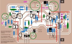
Yet another PCB revision
I slightly modified wakibaki's PCB for my next build. I attached drivers on pcb (requires isolator if using heatsink bar), just remained 6 pads for output transistors. I saved up two wire jumpers 🙄
I populated silkscreen respecting original schematic and added some useful comments.
For those who interest for build one of the PCBs shared in this topic (including this one), posts #56 , #182 , #25 contain useful guide.
Hope you 'enjoy the silence' of Circlophone.
Attachments
Last edited:
Why don't we try something more useful instead?Once you breach the OTA chip no-no, might as well bust out with LM3Whatever output devices. I know you gone there before too, so no playing innocent...
A tidy compact discrete parallel no-ballast power fet output device daughtercard seems useful, like a discrete alternative to. . .
TDA7293V/TDA7294S with the input shorted set to unity gain output buffer, uses slave mode modular parallel listed in the datasheet. The chip is neither tidy nor significantly powerful, but it can parallel without ballast. Can you do it discrete instead?
I also think it is interesting to possibly improve the efficiency a bit so as to reduce the popularity of fan cooling.
I think it would be interesting to see a Small Signal preamp or Headphone sized Circlophone, perhaps with a Jfet input.
I am very sorry, but there is a mistake in PCB posted in 395. Please do not build it that way. (Error: pin of C12 has a short to the jumper wired).
Good point Daniel: the Circlophone is designed to use only 0.25W resistors.
I'm working on a bit of derating at this time and wonder if I've braced up the 25w design to correctly support 180w. Well, there's somewhat a question if it is left switched on for. . . 30 years.
Does it remain true in all conditions, such as 0.25w resistors (and diodes too) never exceeding 42% of their nonstop current capacity and never exceeding their surge capacity, despite my 86v unregulated supply? Or the easier version of the same question: For which resistors is there any excuse to use 1/2w capacity?
How much amperes is seen at D4 when the amplifier is doing 180 watts?
What is a non-zero value for C11 if output devices are TIP35C if I just wanted to know parameters even if it is tiny picofareds? Does having C11 make "reduced risk" of output device explosion?
Which of the tiny capacitors is it important to upgrade and not use ceramic disc?
Can flyback diodes be used for output device protection?
Is there a capmulti accessory could be made with leftover driver compliments (BD139, 2SD669, 2SC2238, 2SC5171, 2sc2073) and leftover output compliments (MJ2955, MJL21193, MJW21195, TIP36C) that aren't used in Circlophone?
P.S.
Progress report:
Accidentally purchased enough parts for five Circlophones, and can now evict the LM3886 infestation from my favorite old stereo receiver. 🙂
Still awaiting BC556B or BC560 and any of 2SC1845, 2SC2240, 2N5551 despite duplicate orders, although plenty of other interesting parts arrived.
From Bigun's modular schematic, figured out how to do the rightmost third on a tiny vertical daughtercard easily held by the to220 shottky's.
I slightly modified wakibaki's PCB for my next build. I attached drivers on pcb (requires isolator if using heatsink bar), just remained 6 pads for output transistors. I saved up two wire jumpers 🙄
I populated silkscreen respecting original schematic and added some useful comments.
For those who interest for build one of the PCBs shared in this topic (including this one), posts #56 , #182 , #25 contain useful guide.
Hope you 'enjoy the silence' of Circlophone.
I like it. You going to build it?
I like it. You going to build it?
Of course, at least two channels. I wonder if I match that silence again. It was very abnormal and I think there is something about this pcb's layout. Surrounded ground? 45 degree intersections and paths? I don't know.
Last edited:
180W on a single pair of transistors is a really tall order ....I'm working on a bit of derating at this time and wonder if I've braced up the 25w design to correctly support 180w. Well, there's somewhat a question if it is left switched on for. . . 30 years.
The resistors dissipating the highest power in the whole circuit are R8, R11 and R24.Does it remain true in all conditions, such as 0.25w resistors (and diodes too) never exceeding 42% of their nonstop current capacity and never exceeding their surge capacity, despite my 86v unregulated supply? Or the easier version of the same question: For which resistors is there any excuse to use 1/2w capacity?
Normally, their dissipation should remain well below 150mW, unless the schottkys you use are really lousy (or are non-schottky).
R17 can be larger than strictly required by power considerations, it will be beneficial.
Approx. 3.2A averageHow much amperes is seen at D4 when the amplifier is doing 180 watts?
C11 is required if the OP devices have a Ft in excess of 20MHz.What is a non-zero value for C11 if output devices are TIP35C if I just wanted to know parameters even if it is tiny picofareds? Does having C11 make "reduced risk" of output device explosion?
Some picofarad will have no effect at all.
With or without, there isn't more or less risk of device explosion.
In general, it can affect the cleanliness of the transitions, and at the extreme, it can avoid oscillations, but of the marginal variety, not susceptible to damage tweeters or the amp itself
Ceramic disc are advisable everywhere. Very low grades like Z5U should be avoided for C6Which of the tiny capacitors is it important to upgrade and not use ceramic disc?
You mean antiparallel diodes on Q8 and Q10?Can flyback diodes be used for output device protection?
Any diode, even a 1N4004 would be OK, you can use "flyback diodes", whatever that is.
You mean a capacitance multiplier?Is there a capmulti accessory could be made with leftover driver compliments (BD139, 2SD669, 2SC2238, 2SC5171, 2sc2073) and leftover output compliments (MJ2955, MJL21193, MJW21195, TIP36C) that aren't used in Circlophone?
I am not too enthusiastic about that: the rails have to be decoupled by good physical capacitors of at least 47µ, and I do not know how the combination of an emitter follower directly connected to a low esr cap would behave.
One could have unpleasant surprises with the resulting impedance.
I am beginning to wonder if a side effect of the quadrature servo couldn't be an indirect reduction of the differential noise level.I wonder if I match that silence again. It was very abnormal and I think there is something about this pcb's layout.
The quietness is really out of the ordinary, and I think it deserves some investigation.
C11 is required if the OP devices have a Ft in excess of 20MHz.
Some picofarad will have no effect at all.
With or without, there isn't more or less risk of device explosion.
My last builds are using Sanyo 2SD1047's (15mhz) and they aren't contain C11. This setup is in usage at least for 4 weeks without any problem. I tested C11 with this setup and I felt slight change in sound signature. Then, I decided to not to use C11 with this setup. This impression is totally related with my setup and may vary with some others.
My first build was blowed up due to insufficent cooling and my speakers has survived after failure of output transistors. So Elvee, in case of a failure at power transistors committed by any reason, is there a risk for throwing rail voltages to the speakers? Yes, Circlophone is such an amp like many others and may contain common risks along with them. Your opinion about applicable dc-protection methods for Circlophone may involve us.
Thanks.
You have been very lucky to get away with your speakers intact.My first build was blowed up due to insufficent cooling and my speakers has survived after failure of output transistors. So Elvee, in case of a failure at power transistors committed by any reason, is there a risk for throwing rail voltages to the speakers?
The circlophone is like any other class B amp, when one output device fails, one of the rails becomes connected to the speaker. Perfect symmetry doesn't extend to failure modes, except when you have a lot of luck.
That's why I think Daniel is playing with the devil trying to extract 180W out of two miserable transistors.
I think protection measures are sensible, good speakers are something precious and need to be protected.Yes, Circlophone is such an amp like many others and may contain common risks along with them. Your opinion about applicable dc-protection methods for Circlophone may involve us.
A simple fuse is enough, since there is no power on or off thump, but the fuse should be inside the feedback loop: that will make it totally transparent from an audio point of view, but it will protect your speakers the same.
That's simple, cheap, effective, and very reliable: exactly want you want here.
A sophisticated protection that refuses to connect your speakers because of some minor malfunction is very frustrating, and it is worse when it misses the coach for the one and only occasion it is really needed.
Here is a document which states that how improving bass response while using a fuse at feedback loop. Do you agree? I very like bass performance of Circlophone and I don't want a compromised solution.
Loudspeaker Fuse Placement for Audio Amplifier to Preserve A Good Bass Response | VIDISONIC
Can you value that optimum fuse (and parallel resistor?) rating for 30-35-40V @8ohms and @4ohms please?
Thanks again.
Loudspeaker Fuse Placement for Audio Amplifier to Preserve A Good Bass Response | VIDISONIC
Can you value that optimum fuse (and parallel resistor?) rating for 30-35-40V @8ohms and @4ohms please?
Thanks again.
Last edited:
Loudspeaker Fuse Placement for Audio Amplifier to Preserve A Good Bass Response | VIDISONIC
Can you value that optimum fuse (and series resistor?) rating for 30-35-40V @8ohms and @4ohms please?
Thanks again.
R3 is there to keep the feedback loop from going crazy and the output stage from failing in case the fuse blows for other reasons than output stage failure, for example because of accidental output short, or if a speaker with too low impedance is used.
Its value must be significantly higher than the speaker impedance because it is in effect parallel with the speaker at all times (and thus dissipates power), but significantly lower than Rf so that there isn't a huge change in the feedback loop when the fuse blows. 220 ohms to 1k is fine.
Unfortunately the "watts" measure has obscured a few details. The speaker and output devices have matching SOA, and with the limiter aligned to ~145w (speaker X-Max) and the amp has a real transmitter heat sink. The voltage will go down from 43 to 41.5 per rail after RF filtering. With harsh use it can sag 2v. That's 39.5v rails. In such conditions the Schottky removes at least the .5. We have 39v rails. And, there is a limiter attack, as well as a thermostatic fan.. . .Perfect symmetry doesn't extend to failure modes, except when you have a lot of luck. That's why I think Daniel is playing with the devil trying to extract 180W out of two miserable transistors.
Do I need to lower the voltage further?
Here is a document which states that how improving bass response while using a fuse at feedback loop. Do you agree? .
No, it will not work: if the fuse opens, R3 will become ~connected to the ground by the speaker's low impedance, thereby opening the feedback loop, just what the scheme is supposed to avoid.
Note that the Circlophone will tolerate it: it will operate as a big power comparator.
These are not the healthiest working conditions, as the output stage will be pushed into deep and hard saturation, causing cross-conduction spikes, but it is tolerable, and the Circlophone will survive.
If you opt for this quick and dirty method, you can completely dispense with R3: see first figure.
This has the advantage of needing no modification, you can just change the way R17 is connected.
The next figure shows the proper implementation, with diodes closing the loop when the fuse opens.
In order not to introduce non-linearities, the peak I*R drop in the fuse may not exceed 0.6V. If this is not the case, 4 diodes have to be used.
It is true that it is technically possible, both from a thermal and SOA perspective, even on a nasty 4 ohm load (with adequate cooling).Unfortunately the "watts" measure has obscured a few details. The speaker and output devices have matching SOA, and with the limiter aligned to ~145w (speaker X-Max) and the amp has a real transmitter heat sink. The voltage will go down from 43 to 41.5 per rail after RF filtering. With harsh use it can sag 2v. That's 39.5v rails. In such conditions the Schottky removes at least the .5. We have 39v rails. And, there is a limiter attack, as well as a thermostatic fan.
But it is also true that most reasonable members of this forum would find crazy the idea of 180W on a single pair of OP devices.
Because you can do something doesn't mean you should....
Attachments
. . .It is true that it is technically possible, both from a thermal and SOA perspective, even on a nasty 4 ohm load (with adequate cooling). But it is also true that most reasonable members of this forum would find crazy the idea of 180W on a single pair of OP devices. Because you can do something doesn't mean you should....
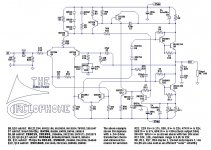
Right. Thank you for putting up with all that. Here, I believe, is the de-rated result, pictured in the schematic attached below.
Please consider this post as a sort of question.
Scenario1: The annotations list a 24+24vac transformer; however, unregulated supplies may wander considerably and daily and may exceed 40v rails temporarily and repeatedly, despite measured actual average at 37vdc rails. Hopefully the derating is now correct to withstand expected power fluctuations?
Scenario2: For documentation purposes, sublist preferential components are in bold, with less suited alternatives in small print, although all items have been scanned for availability. The sublists might need double-checked to remove/replace anything unworkable and/or add anything missing.
The parts selection and schematic should remain valid for many years, except for D7 candidates durable enough to withstand power surge conditions. So far, NXP has BAT86, BAS86 in current production and ESD protected, Vishay has tiny BAT85 but I couldn't confirm sturdy, ST has BAT4x of which BAT46 might outlast a surge, and OnSemi promotes using their 1N5419, which is odd but ESD protected. That's all I could find for D7 withstanding power surges and ESD. I'm curious if the original model had a germanium diode. At maximum (worst case estimated condition) how much voltage and current is seen at D7?
Scenario3: Higher useful power via elegance? Unfortunately, I didn't add your 4n25 based limiter to the schematic (as an accessory part, underneath the annotations), because I didn't know the correct value for the zeners. We discussed adding series variable resistor and 2v? 3v? LED series to 4n25's inbuilt LED, but with that and the 37vdc rails (actual average), I became lost. The schematic below is what I'm using on first build, so I'd love to know the limiter values for soft clip?
Believe it or not, there was much effort involved. Hopefully, this provides some compact documentation. What needs improved?
Attachments
1). Large output devices, running a fraction of capacity, bolted to a good heatsink without thermal compound. 2). Replacing the output devices didn't fix the amplifier.. . .I tried repair old pcb, but couldn't figure out why it didn't work again. After spending too much time then I decided try new one. . .My first build was blowed up due to insufficient cooling and my speakers has survived after failure of output transistors.. . .
Possible cause: Power surge.
Suspected Q12/Q13, D7, D8/D9, D4/D5 one of these failed from overcurrent and/or overvoltage or ESD during power surge conditions. Perhaps you could test to see which need replaced?
Last edited:
D7 is not subjected to any surge, power or otherwise: it simply becomes weakly forward biased when it is clipping.The parts selection and schematic should remain valid for many years, except for D7 candidates durable enough to withstand power surge conditions. So far, NXP has BAT86, BAS86 in current production and ESD protected, Vishay has tiny BAT85 but I couldn't confirm sturdy, ST has BAT4x of which BAT46 might outlast a surge, and OnSemi promotes using their 1N5419, which is odd but ESD protected. That's all I could find for D7 withstanding power surges and ESD. I'm curious if the original model had a germanium diode. At maximum (worst case estimated condition) how much voltage and current is seen at D7?
Even the most fragile HP 5082 xxx would survive any "surge" in those conditions.
C5 is not optional, unless you want to hear crackling noises each time you switch an appliance in your house.
Depends on the degre of warning you want: the pre-clipping indication becomes active when the output comes closer to any supply rail than Vz-1.2-Vf(4N25)-Vf(LED)Scenario3: Higher useful power via elegance? Unfortunately, I didn't add your 4n25 based limiter to the schematic (as an accessory part, underneath the annotations), because I didn't know the correct value for the zeners.
You discussed, I simply said (and I am still saying) there was no reason to use one.We discussed adding series variable resistor and 2v? 3v?
The 4N25 doesn't provide any soft clip: it is drawn to symbolize the output of the clipping detector.LED series to 4n25's inbuilt LED, but with that and the 37vdc rails (actual average), I became lost. The schematic below is what I'm using on first build, so I'd love to know the limiter values for soft clip?
After, you have to add some gain control device of your choice: it could be an LDR-based attenuator, or a Peavey-like circuit, that's up to you.
Last edited:
I can give a try for other alternatives of bias servo transistors in place of my 2n3020's. I wonder is there a beneficial role of Hfe value here? It is not hard to find some BF series high voltage transistors here like BF859/881 etc.
Last edited:
- Home
- Amplifiers
- Solid State
- ♫♪ My little cheap Circlophone© ♫♪