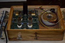
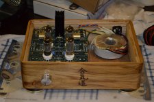
HV applied
With the 220VAC tap in use I have a measured 303VDC on the tubes.
The 6CG7 says 200-300VDC with 350VDC Max.
Am I ok with 303VDC?
The mains power in the house is currently 122VAC once I get it onto my line conditioner I will have a little lower voltage.
However.....I don't claim my meter to be the most accurate on the 600VDC scale.
OK, with no input applied I have hummmmmmm.
Currently I think I have a little grounding issue.
I have not grounded the - side of the RCA's yet and I don't have a ground wire ran from the star to earth prong yet.
Does anybody have any ideas?
Currently I think I have a little grounding issue.
I have not grounded the - side of the RCA's yet and I don't have a ground wire ran from the star to earth prong yet.
Does anybody have any ideas?
The amp will hum with no input connected.
Short the input to ground and it should be quiet, unless you have another problem.
Short the input to ground and it should be quiet, unless you have another problem.
OK here's some points:
1) The max DC plate voltage for the 6CG7 is 300V. But that is per triode! Each triode in an aikido only sees half of the B+ voltage, so each triode is only running at 150V, nowhere near the limit.
2) I don't know what flavor kit you have, but one of the most common causes of hum is not referencing the heaters to 1/4 B+ (or thereabouts). Some of John's boards have the referencing resistors/capacitors included. Others you need to build the voltage divider yourself. You should see this in the documentation.
3) If it's not the hum problem, try removing the first two tubes and see if that changes the hum. That may give some clue as to the source.
Wonderful, thanks for the replies.
I thought that the hum might be because of the no input.
I also read in the manual toward the back that the RCA's should be isolated from the chassis and the ground for them should be attached to the star point.
Well....since my chassis is wood that takes care of the chassis isolation part.
I will attach them to star ground and attach the star ground to third prong.
With input connected I now have a crackly humm.
I have not yet done any extra grounding in the chassis.
I have not yet done any extra grounding in the chassis.
How do you have your pot wired? I found best practice is input to selector switch to pot to Aikido. I just use the ground pointson the board and one ground from the board to star
Input ground to Aikido then input ground from Aikido to pot. Output ground from Aikido to output RCA's.
Input ground to Aikido then input ground from Aikido to pot. Output ground from Aikido to output RCA's.
Last edited:
I have the pot wired to the L&R output.
I don't have any ground attached to the pot.....should I?
I don't have any ground attached to the pot.....should I?
Yessir...I bet that is the issue. Your pot likely has 3 or maybe 4 lugs per channel. input...ground.....output. Use a dmm to make sure. Some have 4 and you ignore one....
I have 3 prongs per output.
I treated this like a standard pot with a Normally High - Output - Normally Low.
I have a Alps Blue Velvet 100k Stereo Pot.
I take it my wiring is incorrect.
I measured the resistance from pin 1 to 2 and had increasing resistance as I turned the knob.
I attached the inputs to pin 1 of ch 1&2 and the outputs to pin 2 of 1&2.
How should I wire them?
OK, so per that diagram I have no earth to my pot, otherwise I have it hooked up correctly.
I will move the pot to the input and add an earth wire from pin3's to star.
Thank You
I will move the pot to the input and add an earth wire from pin3's to star.
Thank You
Do the input/pot grounding through the board first. I had the best results with what I posted earlier.
SAD Day
After running my ground wires I cracked one of my tubes while putting it back in the socket.
BOOOOOOOOOOOOOOO!
Now I need to order another pair.
Double BOOOOOOOOOOOO!
Project on hold until new tubes arrive.
After running my ground wires I cracked one of my tubes while putting it back in the socket.
BOOOOOOOOOOOOOOO!
Now I need to order another pair.
Double BOOOOOOOOOOOO!
Project on hold until new tubes arrive.
Just a little wiggle as i was putting it back in.
Heard a faint tick and noticed the base broke just above the pins. SAD
Luckily the person I ordered these matched pairs from had another.
They test 116/117 on both with 120/120 being 100%.
He was asking $24 +S&H
These have the shield between the plates also which I heard was the good kind.
I snagged them and should have them by Saturday.
I guess the project is on hold for now.
Now I guess I have a spare if I break another.
ARGH!!! sorry to hear that...
What I would do now is use that other one to seat and reseat into the sockets to "break them in"...
I find this helps especially after soldering and to make sure the sockets will freely accept any tube that you want to drop in.
hang in there!
What I would do now is use that other one to seat and reseat into the sockets to "break them in"...
I find this helps especially after soldering and to make sure the sockets will freely accept any tube that you want to drop in.
hang in there!
- Status
- Not open for further replies.
- Home
- Amplifiers
- Tubes / Valves
- My First Tube Preamp

