R17 and 12a/b I remember tweaking a little bit to dial in my B+ where I wanted it.
I seem to remember using the 100 ohm on R17 and somewhere around 2K (4K paralleled) for 12a/b
My advice is start middle of the road and take measurements with the tubes in...
I seem to remember using the 100 ohm on R17 and somewhere around 2K (4K paralleled) for 12a/b
My advice is start middle of the road and take measurements with the tubes in...
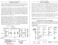
So....That being said, a higher R17 will reduce the B+ since it is in a series circuit with R12a/b?
It looks like there is a capacitor tied in there between R17 & R12a/b, is that some sort of a voltage divider circuit?
Does that capacitor have anything to do with the B+ level?
Should I start with one of the middle values that were supplied (200Ω or so) instead of the 470Ω that I used since it fell between the 10 & 1k values?
Its really just a CRCRC filtering of the B+ Capacitors will have an effect on the B+ but the standard values are just fine.
Really as long as you land somewhere between 250 and 300 or so that is the key. The voltage with the tubes out will be much higher since there will be no current flowing. Once the tubes are in and all running at ~10mA you can calculate what the drop will be calculating the values of R17 and R12a/b. V=I*R
Really as long as you land somewhere between 250 and 300 or so that is the key. The voltage with the tubes out will be much higher since there will be no current flowing. Once the tubes are in and all running at ~10mA you can calculate what the drop will be calculating the values of R17 and R12a/b. V=I*R
I figured running my 220V tap with 311V Raw B+ then I chose the 18V drop value for R12a/b left me with 293V that was pretty close.
It seems that most people recommend running the 6GC7 at as close to 300V as possible.
It seems that most people recommend running the 6GC7 at as close to 300V as possible.
Hopefully this weekend I will have some time to build the last few spacers for the power supply support.
Then I can install the power button, IEC socket & volume control.
Once that is finished I can put the roundovers on the corners and oil the chassis.
I'm really hoping to begin testing this weekend.
Then I can install the power button, IEC socket & volume control.
Once that is finished I can put the roundovers on the corners and oil the chassis.
I'm really hoping to begin testing this weekend.
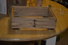
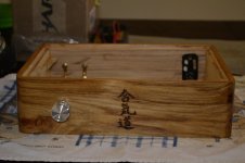
Chassis Finished, Final Assembly Begins
I have finally completed assembly.
After a bunch of holes, 4 coats of Tru-Oil & 2 coats of gun stock wax......Here She Is!
This was truly a time consuming yet very rewarding process.
Who would think a few pieces of hardwood flooring would look so good with such a simple finishing process.
I have finally completed assembly.
After a bunch of holes, 4 coats of Tru-Oil & 2 coats of gun stock wax......Here She Is!
This was truly a time consuming yet very rewarding process.
Who would think a few pieces of hardwood flooring would look so good with such a simple finishing process.
Attachments

Power Wiring Help
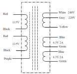
I am in need of help, I think I have the heater power figured out but my power transformer has a single 220v output no CT.
Does my HV wiring look good?
I have the 220v tap to the B+ pad with the ground of the 220v tap to the CT pad.
Is this correct?
Here is my transformer, Antek - AS-05T240.
I am in need of help, I think I have the heater power figured out but my power transformer has a single 220v output no CT.
Does my HV wiring look good?
I have the 220v tap to the B+ pad with the ground of the 220v tap to the CT pad.
Is this correct?
Here is my transformer, Antek - AS-05T240.
Attachments
with the ground of the 220v tap to the CT pad.
I guess so, if your yellow goes to your ground pad/point
might cause confusion to use the term CT pad
on trafo its called CT, and only there
in relation to supply caps, or amp curcuit, its just ground
I think you got it wrong - I would have thought that the yellow/gray wires would go to the two pads "HV B+ AC"
I think you got it wrong - I would have thought that the yellow/gray wires would go to the two pads "HV B+ AC"
yes, sorry
got confused by the term CT was being used
I was generally speaking, about CT
but here there is no CT
and then both AC goes to bridge rectifer, ofcourse
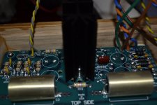
I/O Wiring
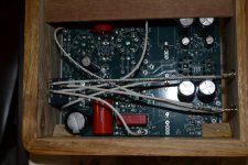
Here is some pictures from the underside of the Preamp.
I have chosen to use RG316 for my I/O wiring, it's nice and small with silver plated copper conductor & shield.
It is very nice to work with and its Teflon dielectric & jacket make it suitable for high temp use.
Here is some pictures from the underside of the Preamp.
I have chosen to use RG316 for my I/O wiring, it's nice and small with silver plated copper conductor & shield.
It is very nice to work with and its Teflon dielectric & jacket make it suitable for high temp use.
Attachments
Crackle
OK....I have plugged it in with heater power only I hear a very faint crackling sound.
I unplugged the unit and started feeling for hot capacitors....did not find any that were warm even.
I then checked for polarity and found all capacitors were proper polarity.
Where should I look next?
Should I plug it back in and test the heater voltage to make sure the regulator is working?
OK I think I have the crackle taken care of.
I removed the CT for the heater because at closer inspection I discovered that I have configured heater for FWB w/o CT.
After I removed the CT I tested again and heard no crackling.
The Heater +- measures 6.28VDC, Perfect for my 6CG7's.
Now I'm on to testing the heater with tubes installed to make sure there is no large voltage drop when the regulator is loaded.
- Status
- Not open for further replies.
- Home
- Amplifiers
- Tubes / Valves
- My First Tube Preamp