BrianGT said:
25mm. The kits will come with Panasonic 10,000uF 50v caps for the power supply boards. The snap-in types, with 2mm holes spaced 10mm apart.
25mm ?? 😱

I have not been able to find 10,000uF 50V caps smaller in diameter than 35mm! What Panasonic type are you using, and where can I find them?
Cheers.
Hi Brian,
Looking good. 😉
Here's a couple more ideas for you NOT to use. 😀
1. I still think R3/R4 should be to the side of the filter cap as it gives you a more compact design.
2. Also to make the design complete, why don't you add a "power on" LED and resistor. This LED would indicate power on and the charge status of the cap. It would also help the cap discharge process. This could be located close to R3/R4. Allow people to have the LED on board or run wires to the front panel.
falcott said:25mm ?? 😱
I have not been able to find 10,000uF 50V caps smaller in diameter than 35mm! What Panasonic type are you using, and where can I find them?
Digikey - Panasonic TS series:
http://dkc3.digikey.com/PDF/T051/0875.pdf
Board now supports 30mm caps as well
grege said:Here's a couple more ideas for you NOT to use. 😀
1. I still think R3/R4 should be to the side of the filter cap as it gives you a more compact design.
2. Also to make the design complete, why don't you add a "power on" LED and resistor. This LED would indicate power on and the charge status of the cap. It would also help the cap discharge process. This could be located close to R3/R4. Allow people to have the LED on board or run wires to the front panel.
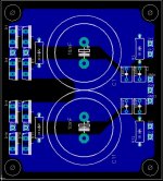
Here is a screenshot of the board with R3/R4 on the side to allow for 30mm caps. I will look into adding the resistor for the LED. I had planned on doing this a while back, but forgot about it.
--
Brian
Attachments

curva said:what about t-network? optional buffer?
i think the goal of these kits is simplicity. its also the essence of the gainclone, low part count, short singal path etc. adding a buffer to the kit would just complicate it too much. it would also increase the price and burden on Brian.
Brian, i'm actually getting some of theese boards with the good grace of steenoe, but would you mind making it possible for 35mm caps? i swear to 80v caps for reasons unknown, and would like to have it my way 😉
but how about some traces for easy implimenting some regulators as well? it should not take up much space..
but how about some traces for easy implimenting some regulators as well? it should not take up much space..
demogorgon said:Brian, i'm actually getting some of theese boards with the good grace of steenoe, but would you mind making it possible for 35mm caps? i swear to 80v caps for reasons unknown, and would like to have it my way 😉
but how about some traces for easy implimenting some regulators as well? it should not take up much space..
I am looking into the possibility of 35mm caps. The layout currently supports 25mm and 30mm caps.
As for the regulators, Why would you need traces, just run the output of the board into a regulator, and then the output of the regulator into the amp board. I am sure you could prototype something. Regulators are not going to be used in the kit that I will be providing.
--
Brian
I reworked the layout again, and here is a version that would support 25mm, 30mm and 35mm caps (snap-in type with 10mm lead spacing and 2mm holes are provided for mounting leads):
BLUE = bottom layer, RED = top layer
I didn't add any heat-relief traces yet for the components mounted to the main planes (or beefy traces), and I am considering this now.
I am now leaning more towards making the LM3886 pcb set the same size as the LM3875 pcb set with normal rectifier boards, and offering the "snubberized" pwr supply pcb seperately, to allow for more flexability. Any comments?
--
Brian
An externally hosted image should be here but it was not working when we last tested it.
BLUE = bottom layer, RED = top layer
I didn't add any heat-relief traces yet for the components mounted to the main planes (or beefy traces), and I am considering this now.
I am now leaning more towards making the LM3886 pcb set the same size as the LM3875 pcb set with normal rectifier boards, and offering the "snubberized" pwr supply pcb seperately, to allow for more flexability. Any comments?
--
Brian
any chance you might be able to add a trim pot to adjust the DC offset? Would that wind up effecting the sound of the amp if you did?
Evilsizer said:any chance you might be able to add a trim pot to adjust the DC offset? Would that wind up effecting the sound of the amp if you did?
This will not be done on the pcb, as I want to keep a simple setup, and I do not know the sonic effects of what you are referring to. I haven't encountered any DC offset problems, and my current LM3875 amp has about 60mV per channel and works fine.
--
Brian
Upupa Epops said:To Brian : " You too, Snubbrutus ? " 😀
Seems worth trying... and I have wanted to try a higher capacitance power supply.
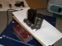
Here is a mockup of the pcb in the actual size with 35mm caps installed on the pcb. Board width is the same as the current LM3875 boards:
--
Brian
Attachments

To Brian : Why are you using two rectifiers ? It have sense only in case, if you can use voltage regulators and have only one polarity one. With center tapped and center grounded transformer you get the same ripple effect by better efficiency. " Ringing " on both rails you can in this case dump by +/- bypasing capacitor, 'cos " ringing " periode is on both rails in opposite polarity.
BrianGT said:I am now leaning more towards making the LM3886 pcb set the same size as the LM3875 pcb set with normal rectifier boards, and offering the "snubberized" pwr supply pcb seperately, to allow for more flexability. Any comments?
I think that is a great solution, much easier for you than custom matching boards. So i guess the LM3886/LM3785 would be similar to the kits offered in the past. Which means one could buy a single snubbered supply board with the components not offered on the standard kit for an extra cost.
Snubber board really looking great!
BrianGT, are you planing to build an regulated PSU for that amp ?
The last PCB looks really nice 😱 😀 Thanks for upgrading for 35mm caps 😎
Do you have any ideia when it could go in to the "market" ?
The last PCB looks really nice 😱 😀 Thanks for upgrading for 35mm caps 😎
Do you have any ideia when it could go in to the "market" ?
- Home
- Amplifiers
- Chip Amps
- my first try at a LM3886 layout, any comments/suggestions?