Hi,
attached you will find some Pictures
the film dimension will be 130cm *30cm D/S 3mm for the bass
for the tweeter 130cm *10cm D/S 1mm
the XO will be set to 1000Hz
the tweeter will be done by segmented wires H0V7-U 1,5 mm² 2*230v/6V 50VA ring transformer
the bass i will do by a perforated metal plate Rv5-8 24*230v/24V 5VA print Trafos
any recommendation?
Best regards Paul
Attachments
Hi,
 😉
😉
- if You choose for a electrically segmented stator, a single large stator will do equally well as a multi-stator thing, but with less hassle and less effort.
- H07VU is a fine choice for Bass panels where the large diameter -and associated increased spacing between the wires- doesn't compromise performance. For a mid-high with its smaller d/s choose smaller diameter wire like H05.
- I regard a punched metal sheet stator not a good choice for Bass panel application. It remains a major problem to apply a safe and reliable insulative coating. RV5/8 is a industry standard punching pattern and might allow for thicker coating than with smaller RVs, but a wire stator using H07 wire would still be my first thought instead.
- 130x30cm -or x40cm if one adds the Highs-panel- is not enough for serious Bass reproduction. Its just enough for a decent dynamic range >>100Hz and simply too small for lower bass. To increase d/s is a desperate but useless attempt to lower the low bandwidth limit or to provide for at least a bit of dynamic range. The small size means even less reason to divide into two different panels.
- 130cm panel height is already so much that -added a frame- the speaker will be noticed as an 'object or obstacle' in front of You. Increasing height won't spoil matters further optically, but would be advantageous acoustically. I'd suggest to increase panel height to at least 160cm, rather 180-200cm, choose a width around 40cm, a d/s of <3mm, and a (optically) thin holding frame and of course a single segmented wire stator panel. And to make things round, add a decent subwoofer for the range below 100Hz. 😉
jauu
Calvin
Yes, forget the above design criteriaany recommendation
😉- if You choose for a electrically segmented stator, a single large stator will do equally well as a multi-stator thing, but with less hassle and less effort.
- H07VU is a fine choice for Bass panels where the large diameter -and associated increased spacing between the wires- doesn't compromise performance. For a mid-high with its smaller d/s choose smaller diameter wire like H05.
- I regard a punched metal sheet stator not a good choice for Bass panel application. It remains a major problem to apply a safe and reliable insulative coating. RV5/8 is a industry standard punching pattern and might allow for thicker coating than with smaller RVs, but a wire stator using H07 wire would still be my first thought instead.
- 130x30cm -or x40cm if one adds the Highs-panel- is not enough for serious Bass reproduction. Its just enough for a decent dynamic range >>100Hz and simply too small for lower bass. To increase d/s is a desperate but useless attempt to lower the low bandwidth limit or to provide for at least a bit of dynamic range. The small size means even less reason to divide into two different panels.
- 130cm panel height is already so much that -added a frame- the speaker will be noticed as an 'object or obstacle' in front of You. Increasing height won't spoil matters further optically, but would be advantageous acoustically. I'd suggest to increase panel height to at least 160cm, rather 180-200cm, choose a width around 40cm, a d/s of <3mm, and a (optically) thin holding frame and of course a single segmented wire stator panel. And to make things round, add a decent subwoofer for the range below 100Hz. 😉
jauu
Calvin
Hi Actimel
What Calvin said...
Additionally, make it symmetric (transformer connected to middle segment). It will have a much better off-axis response.
If 2m high sounds a bit unmanageable, think in terms of two 1 m sections stacked on top of each other. If you keep total height below curtain rail height, WAF wont be compromised too badly.
regards
Rod
Good Morning,
the frame i will do by 5cm wide plexiglass
as ordered i will not use perforated steal plate 😉
and for tweeter section i will go for H0V5-U but which one you would go for 1mm²? 0,75mm²? 0,5mm²?
what i don't get in my mind
were is the different??
between a large surface with a small membran displacement or a smaller membran with a larger membran displacement??
not thought in the phase cancellation
for bass i thought finally it is all about air displacement..?
Regards
Hi,
the key to successful ESL-building is efficiency.
Efficiency drops with every 1/10mm more of d/s.
This alone speaks in favour of larger membrane size against larger excursion.
Then there´s the problem of acoustic impedance or how well the membrane is coupling to the surrounding air.
In short, a membrane with dimensions large compared to the wavelength couples very good to air.
As dimensions are comparable or smaller as the wavelength the acoustic impedance becomes complex, which simply means that only a fraction of the membrane´s energy can be transferred to the air.
So again, increasing membrane dimensions is more favourable than increasing excursion.
Third there´s the effect of acoustic phase cancellation which also requires more of displacement volume.
And lastly is the ESL only the verylow-THD transducer if the excursion can be kept below +-0.5mm.
At latest from +-1mm on THD ´explodes´.
Luckily is a large membrane area with a ESL much easyer to build and in a more eye-pleasing/styish fashion than with dynamic speakers and one can simply optimize active membrane area over passive baffle size or cabinet volume.
jauu
Calvin
thanks for that clear words
so for a ESL more than ~ 1/1,5mm d/s is just useless!
for tweeter
what does you think about this wire?http://www.conrad.de/ce/de/product/1180316/Litze-LiFY-1-x-025-mm-Gruen-Conrad-93030c14-25-m?ref=list
the coating around is just ~0,25mm thick
with a wire like this a d/s about 0,75mm should not be so difficult to built
Regards Paul
Hi,
1) Stranded wire is not recommended in case you plan to use horizontal supports as opposed to light louvre material. It tends to unwind, lose tension and is generally not as stable as single core material.
2) As long as wire diameter and wire-to-wire spacing is in similar realm as D/s spacing, it is a good start. Generally, for a D/S spacing like 1.5 mm and more H05 single core, black wire with lets say 30 to 40% of open area is perhaps good enough for both high and low range. Actually, if you would measure the capacitance of stators it would be extremely close to as if it were just plain sheets of metal. It's kind of "grid effect" and is quite surprising.
3) Copper area does not necessarily lead to higher efficiency but larger diameter allows higher distance between cross bars.
4) A crucial thing to success is a wire stretching machine. It's quite simple to build one using threaded rods. Wire should be stretched into plastic deformation zone, which straightens it very well and also causes cold-hardening effect. Of course it should not be bonded to supporting structure under high stress, as the structure itself may fail due to high tensile force of many wires combined
5) As already noted, better to stay away from metal sheets and bass panels. Very, very difficult to make proper insulation against arcing.
6) in case of segmented ESL, it's better that high frequencies are dispersed from the center, gradually lowering towards sides. In comparison, when it's dispersed from either side of an ESL, dispersion is different while moving from one to other side of the speaker. The subjective effect of this may sound very weird, depending on exact configuration.
7) Voltage rating of the wire is not critical in most ESL applications.
Even 300/500V rated H05 wire can typically handle many times it's rated voltage. However the quality of insulation is still a significant factor. Buy few samples from different manufacturers, do a longitudinal cut with a sharp knife. Visual inspection helps.
8) If you plan to use cross bars and not light louvres, try to use as thin as it's practical in mechanical and ease-of work terms. 6mm is acceptable , < 4mm is good but 1cm thick is too much. One hypothesis behind this is air turbulence, another is diffraction. Perhaps it's a combination of both.
9) Again, as already noted, it's good if radiating surface extends above the ears, meaning panel height ~> 2 meters. Subjectively this configuration sounds better compared to a shorter panel which is tilted.
Regards,
Lukas.
Last edited:
Dear Gerald,
thank you for the link´s
the 2:nd ESL-attempt tread is very informative and present a handsome built
so you recommend me to do a square wave test to qualify my bass step up transformers
i´m using REW what settings should i put in to the spl Generator?
i can measure only Sound output dataset
also till know i could not find were i can measure like an ozilluskop is this possible with RWE?
Regards Paul
A square wave can tell you a lot about the characteristics of most any device being that of just components and amplifiers and other devices.
I don't have any specific's about using REW it took me a while with just plugging around to finally understand and use it as I was suffering along with the some of the many bugs it had along the way.
I haven't had the chance lately to mess with the newest version but it did work much better than some of the older ones I was using that had lots of bug fixes along the way.
If you want a good scope/RTA type program Visual Analyzer is probably your best bet.
A lot of these programs that I have been using for many years may be destined to become paid versions at one point or another, so try to grab any and every copy that you may find if funds are tight.
Wavespectra 1.51 is one of the best and fastest SCOPE/RTA programs I have seen but the links have been moved.
It can still be found but for a very small fee now, and the webpages are Chinese I think so you need to use Google translator or something to view them, But they are there and I have just found them again a few weeks ago.
REW has a recorded waveform viewer but it is not Realtime like VA or Wave Spectra.
I just found this that I will have to checkcout!! 🙂
It is quite expensive but in the past I have found the only option at times was to just format my drive and reload the OS and software ever 30 days in order to keep using it!
But the good thing is that there are many viable free programs that are just as good to use.
SpectraPLUS - Home Page : Acoustics and Vibration : FFT Spectrum Analyzer : SpectraPlus.com
Here is where I had found a lot of stuff before and have tried out nearly everything here that I could get a download.
Many may be dead links unless the page has been updated but it is worth looking at,
Spectrum - Software: Spectrum analyzers
jer 🙂
Last edited:
Hi,
i was being on a business trip
i will do some test at weekend..
does someone know a company where i can buy some louvre panels in germany or europe?
Regards Paul
i was being on a business trip
i will do some test at weekend..
does someone know a company where i can buy some louvre panels in germany or europe?
Regards Paul
Hi,
One of the best programs I have seen for measurements of speakers is ARTA. It is quite advanced and has many features other software does not have, also not difficult to learn. It's not free, however, but IMO worth the investment.
About square wave measurements on loudspeakers, I disagree. No mechanical music instrument can produce a perfect square wave. Electronic synthesizers is not a mechanical instrument, still it is typically designed to filter out ultrasonic harmonics(>>20 kHz) that a perfect square wave has. IMO feeding your speakers with electrically generated square and then measuring it is quite a bit of a moot point. What really important is, a) extra noises, b) frequency response, c) harmonic & intermodulation distortion d) spectral decay
Regards,
Lukas.
Hi,
the squarewave behaviour reveals many details of the transducer's behaviour, like amplitude response, phase response, bandwidth, etc. with a high degree of sensitivity.
If the transducer is a amplifier the output is still recognizable as something squareish, even if that device is not wide banwidth ... think of Tube amps or CD-players.
With most speakers this is not the case, because a speaker can't reproduce a static air pressure, store and release energy, and because of delays and phase issues of drivers and xovers.
This leads to a response where the output may not even be recognized as a square at all and which may change in shape alot with varying base frequency.
Strictly seen it only prooves how far off of the perfect transducer a typical speaker still is, or that the square is too sensitive.
It also prooves the insensitivity of our hearing regarding phase issues.
Still though will a speaker with a better square response also show better behaviour in more common measurements (amplitude response for example).
In that the square contains the same information as other measurements but is more difficult to interprete and that for most speakers it just looks horrible, it's obvious that it is less commonly used.
jauu
Calvin
As Gerald says, sq waves jet-propel assessing gear. Looking at how an amp handles sq waves tells us a lot (and shows infra- and super-sonic wiggles too). If you pump in a sq wave to an amp at 200 Hz, the device under test has to handle 20 to 2000 Hz to make it look square on a scope.
And as Calvin says, I've never seen anything that looked much like a sq wave from a speaker of any sort. But if a speaker can handle the passband, why shouldn't the sq wave look good? Of course, I've seen speakers do impressive pulses and wave-train envelopes.
(BTW, a trusted buddy says he did see creditable sq waves from a later Quad with round seqmented stator. A very impressive feat.)
Ben
Last edited:
Hi,
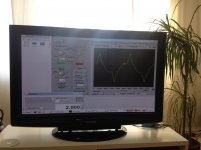
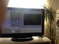
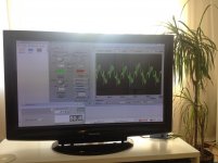
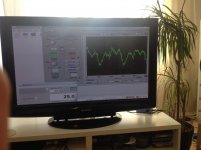
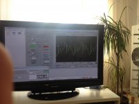
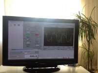
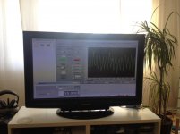
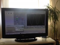
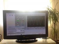
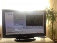
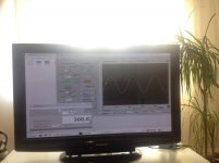
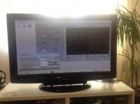
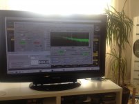
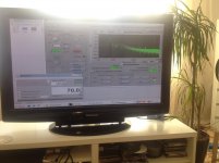
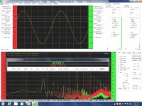
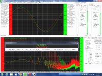
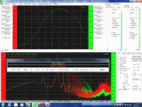
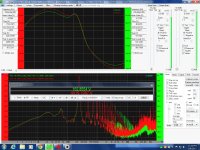
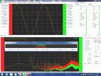
i have done some measurements
i have forget to monitor the input Signal
however with some Fantasy you can see the squarewave 😉
the measurements are done inside my living room
the microphone are placed in ~2m distance to Speaker
at lower frequency the Sound Level is Close to film Stator collapsing so the displacement should be about +- ~0,7-0,9mm
what i do not know is how well the microphone is measuring but i guess the measuring failure is ignored because the biggest failure is coming from the speaker itself
also there is some Peak what i do not understand
sadly i have no electrical reverence measurement after the transformer
the measurements are done to qualify the quality of the 24*5VA transformer
the XO is set to 800 hz 12db/okt
for tweeter section is about 1000hz 24db/okt
does someone have some similar measurements to compare it?
of course not with a hybride solution
Best regards Paul
Attachments
-
 square 200hz.jpg509.9 KB · Views: 150
 -
 square 100hz.jpg493.7 KB · Views: 150
 -
 square 50hz.jpg531.6 KB · Views: 150
 -
 square 25hz.jpg495 KB · Views: 160
 -
 square 250hz.jpg499.1 KB · Views: 137
 -
 square 500hz.jpg505.1 KB · Views: 68
 -
 square 1000hz.jpg484 KB · Views: 68
 -
 square 10000hz.jpg487.6 KB · Views: 70
 -
 square 5000hz.jpg517.1 KB · Views: 73
 -
 square 15000hz.jpg508.3 KB · Views: 64
some sinewave and THD measurements
Attachments
-
 30hz sine.jpg481.2 KB · Views: 72
 -
 50hz sine.jpg465.1 KB · Views: 74
 -
 100hz sine.jpg514.7 KB · Views: 73
 -
 300hz sine.jpg444.9 KB · Views: 73
 -
 500hz sine.jpg471.2 KB · Views: 67
 -
 THD 800hz.jpg497.3 KB · Views: 72
 -
 THD 70hz.jpg535.7 KB · Views: 66
 -
 THD 50hz.jpg588.7 KB · Views: 66
 -
 THD 30hz.jpg481.6 KB · Views: 66
 -
 1000hz sine.jpg454.4 KB · Views: 74
I had done such measurements of just a single Antek AS(AN)1206 transformer and the 200wat bergin core that i have been using.
Both compare similar results between the two and this shows me that good quality iron is used now days for even just power transformers today unlike the ones from yesteryear.
I had all of my plots at ESL DIY but when they revamped the site they lost them all!!
However I still have them scattered in my archives, I will try to find them later for you to compare.
From memory I got a figure of .5% THD right at the edge core saturation at about 300-360HZ and 40Vrms.
This is the point were the saturation knee is just starting to form and is in equal amplitude with the Sine wave's peak.
Sonically I couldn't really much hear this distortion when the ESL was hooked up, for this is the point where the transformer itself is starting to sing although I could hear that plain as day.
At above that frequency past saturation this THD dropped starting at .1% THD at 400HZ down to .05% by 500-600hz.
And by 1Khz and above it was basically unmeasureable to the limits of my sound card at .005% THD or better.
I was using my Crown DC300a to drive the transformer so the THD measurements seem to maybe reflect that of the amplifier itself so it wasn't the greatest compared to my other amplifier an Ashely FTX200 at a rated .007% THD but it sufficed.
I used REW and VA to make those plots as well as HOLMs.
I like REW becasue it gives you a breakdown of all of the harmonics from the point of the cursor lines position.
VA and WaveSpectra show the results in real time for whatever frequency you are using and I have not yet figured out how to Plot a THD vs Freq. only curve in VA yet.
I used a Voltage divider to measure the voltage directly coming out of the transformer at 4.5Kvrms straight in to my sound card.
I have explained that setup in another thread and the full build is on ESLDIY but again the pictures are gone.
At the time I had used the onboard sound system on my ASROCK 990FX Extreme 4 motherboard.
Since then I now have been using my Gina24/96 card for my audio device and measurements.
There was something going wrong using the onboard system with random glitch's in the measurement curves.
Many have complained about this type of thing in the past I have not figured out what is causing this on my end either.
FWIW
jer 🙂
Hi,
It also prooves the insensitivity of our hearing regarding phase issues.
jauu
Calvin
Hi,
I completely agree with your point. However I'm not sure if it's really "insensitivity" or adaptations of sound-resolving part of the brain.
If we were sensitive to phase shifts.. Well then it would be extremely confusing as frequency-dependant phase shifting is always introduced when distance is changed from a sound source which is producing multiple frequencies. In close field(low compared to the wavelength) a phase could be more or less coherent. But move, lets say, to 0.5 meter. At 50Hz there may be no really significant phase shift. But at, lets say, 10 kHz. The phase would be shifted by many times 360 degrees(I'm not an expert in math, but my calculations show ~14.535 times, or ~5232 degress). Anyone could point out an error ?
Regards,
Lukas.
Hi,
i thought someone would write something like:
the measurement looks totally rubbish compare it to my measurement!
or
the measurement looks ok similar my compare it to my measurement!
can someone present a square wave measurement of his on FR ESL at 50Hz please
as fare i get it the acoustical square wave measurement present to things
1. impulse response
2. bass capacity
best regards Paul
I found the charts of the measurement I have done using an Antek AS(AN)1206.
This set shows the FFT and output voltage, and primary voltage waveform's using Visual Analyzer.
Each screen shot is caption labeled of the conditions of each test.
The knee in the waveform is caused by the raised current of the onset of core saturation and they show how it goes away as the frequency is raised.
These testes were at about 36Vrms using my Crown DC300A with the primary set for 6Vrms connenctions.
jer 🙂
Attachments
-
 AS 1206 output test 2400hz sine.jpg357.7 KB · Views: 79
 -
 Onset of core satuation at 40Vrms 330Hz.jpg737.5 KB · Views: 92
 -
 Onset of core satuation at 40Vrms 304Hz.jpg743.4 KB · Views: 84
 -
 Onset of core satuation at 40Vrms 270Hz.jpg742.5 KB · Views: 102
 -
 Onset of core satuation at 40Vrms 240Hz.jpg737.2 KB · Views: 68
 -
 AS 1206 output test 2400hz sine b.jpg367.8 KB · Views: 73
Last edited:
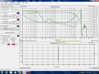
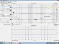
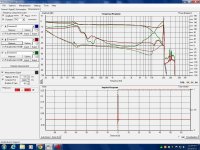
This set is of the same test session but using REW and HOLM.
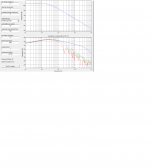
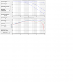
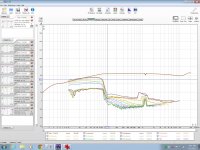
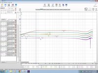
These a various graphs of frequency response and THD of series (12v) and parallel (6v) primary connections and the 120v windings in series and a couple of the in parallel at several voltage input levels at 5Vrms, 10Vrms, 20Vrms and 40Vrms.
All of the measurements were taken directly from the output of the transformer.
The graphs for the primary set for 12Vrms show a prominent dip in the frequency response at about 12Khz or so.
jer 🙂
Attachments
-
 HolmsImpulse FR-THD-Phase Transformer 20Vrms input.jpg671.9 KB · Views: 79
 -
 AS 1206 Saturation at 20v-10v-5v peak input 12v primary.jpg329.8 KB · Views: 70
 -
 FR of AS-1206 Hv windings in series.jpg361.3 KB · Views: 69
 -
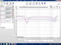 REW FR minus 24-18-12-6 db 40Vrms.jpg481 KB · Views: 73
 -
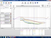 REW THD -24db 40Vrms.jpg559.7 KB · Views: 80
 -
 THD at 20Vpeak-14.14Vrms 6V primary.jpg276 KB · Views: 76
 -
 AS 1206 Saturation at 20v-10v-5v peak input 6v and 12v primary.jpg278.1 KB · Views: 73
 -
 HolmsImpulse FR-THD-Phase Transformer-Green -20Vrms amp out-red.jpg677.5 KB · Views: 82
Last edited:
- Status
- Not open for further replies.
- Home
- Loudspeakers
- Planars & Exotics
- my first esl measurments questions