a lot of input....🙄
maybe i should go for a lot smaller design but this will limit the bandwidth of this speaker
that's a very nice offer!! thanks
regards
maybe i should go for a lot smaller design but this will limit the bandwidth of this speaker
that's a very nice offer!! thanks
regards
Hi,
the biggest effect of a smaller panel is a lowered dynamic range.
As a extreme think of headphones.
The (lower) bandwidth is only related to the base resonance Fs.
Fs is a result of the amount of mechanical tension and free vibrating membrane distance.
A smaller panel with a width of say 15 cm and low diaphragm tension may have a Fs of 60Hz, while a 50cm wide panel with high tension and additional spacers placed every 10cm may have a Fs of 120Hz.
While the small panel actually has a greater bandwidth than the larger panel, the maximum SPL (dynamic range) may be 10-15dB less.
I suggest to choose the membrane area still as large as possible, but to vary the height-width relationship towards more height and less width.
The reasons are following:
- greater width of a panel requires greater listening distance until the impression of stage develops. Lower distances sound like a oversized headphone.
- the frequency range down to which the panel sees a real acoustic impedance -hence optimally coupling to the air- lowers
- the dipolar cylindrical distribution character reaches down lower in frequency. As room modes are most disturbing in the low frequency range, the cylindrical wave shape reduces the negative impact of (vertical ) modes and eases positioning or setting up the system due to lowered influence of the floor and the ceiling.
- a less wide panel will show higher mechanical rigidity and less rattle, assumed that a stiff mounting frame fixates the panel in vertical direction.
- optical impression improves
jauu
Calvin
Last edited:
again some nice Input 🙂
i thing, i need to go some processing steps back!
my living room:
wide ~5m
length ~6m
high ~2,4m
the speaker will be placed in a distance of 1m to each corner
the listening distance will be about ~4m to both of the two panels
what width of panel is recommended in my case?
and the high i guess should be as high as possible! right??
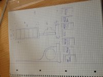
i also was getting a very nice idea how to build the frame but i was so endless busy this days... i will do a drawing
however now i will enjoy my weekend and i hope you do the same
with that words CHEERS
Paul
i thing, i need to go some processing steps back!
my living room:
wide ~5m
length ~6m
high ~2,4m
the speaker will be placed in a distance of 1m to each corner
the listening distance will be about ~4m to both of the two panels
what width of panel is recommended in my case?
and the high i guess should be as high as possible! right??
i also was getting a very nice idea how to build the frame but i was so endless busy this days... i will do a drawing
however now i will enjoy my weekend and i hope you do the same
with that words CHEERS
Paul

Transformer
Hi,
I got a question about transformer.
As far I have understand I can calculate as follow
If I use one transformer 230v/12v @50Hz
Then I can feed the transformer
12v @50hz
24v @100hz
48v @200hz
And 6v @25hz is this correct?
Also how is the behavior if I use more then one transformer?
I using a lot of smale 5va 230v/12v trafos 12v side connected in parallel and 230v side in serie I get zero output below 50hz is there a simple reason why?
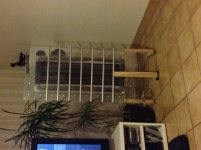
The actual panel size is 20cm *70cm d/s 1,5mm
Attached a picture
Best regards Paul
Hi,
I got a question about transformer.
As far I have understand I can calculate as follow
If I use one transformer 230v/12v @50Hz
Then I can feed the transformer
12v @50hz
24v @100hz
48v @200hz
And 6v @25hz is this correct?
Also how is the behavior if I use more then one transformer?
I using a lot of smale 5va 230v/12v trafos 12v side connected in parallel and 230v side in serie I get zero output below 50hz is there a simple reason why?
The actual panel size is 20cm *70cm d/s 1,5mm
Attached a picture
Best regards Paul
Attachments
Yes, You are correct at the feeding the transformers at the voltages you have stated as per lowest frequency before saturation occurs.
Using 5VA transformers may work only to a limit and not at all very well for the lowest frequency's.
It takes a lot of iron to get decent performance in THD at low frequency's.
Also since the primary's inductance depicts what impedance the amplifier will see at those frequency's it will quite low as well and even lower every time you add another primary winding in parallel!
Two things that can be happening providing that the transformers are still working and are not shorted or open, is that the performance at 50hz is so low that dipole cancellation is causing you not to hear the signal.
As I mentioned the impedance may also be so low at that frequency that the amplifier can not produce enough voltage swing to make a difference.
Even a single Antek AN-1206 has an impedance of less than 1 ohm at 60hz using the 6v winding as shown here,
http://www.diyaudio.com/forums/planars-exotics/161485-step-up-transformer-design-6.html#post3404300
So to parallel another primary this impedance would be cut in half again not to mention the onset of core saturation at only 12Vrms.
It is also likely that with a 5VA transformer the windings will be of a very thin gauge wire and will not last long (if at all) for such heavy current surges from the amplifier.
jer 🙂
Hi, 🙂
I was using a multimeter to measure the output voltage
But the multimeter was so rubbish that it was not able to measure a voltage lower than 50Hz
However I do get some output
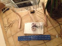
I using 24 of this smale transformers (230v/12v 68%) waht will give a step up about ~300
This is working ok up to ~2000hz
Also I was able to equalize the dipole cansellationn but for real depp bass the film was running into the stators at about ~20/25Hz
Has ever build someone a real tow way esl?
Regards
I was using a multimeter to measure the output voltage
But the multimeter was so rubbish that it was not able to measure a voltage lower than 50Hz
However I do get some output
I using 24 of this smale transformers (230v/12v 68%) waht will give a step up about ~300
This is working ok up to ~2000hz
Also I was able to equalize the dipole cansellationn but for real depp bass the film was running into the stators at about ~20/25Hz
Has ever build someone a real tow way esl?
Regards
Attachments
Hi,
By using so many transformers you should watch for at least several things :
a) Very high step-up ratio might make LC resonance(leakage inductance vs transformer parasitic capacitance+C of the panel) below 20 kHz. This would show up as a peak and then very sudden drop at high freqs above this resonance.
b) The reactive load at high frequency could drop well below 1 ohm. This may or may not give problems for the amplifier to drive(since peak and average level drops with frequency), but at least, it causes some weird effects. For example, the gauge, impedance(and thus especially length) of wire from amplifier to to the speaker may influence the output at treble significantly.
c) small trannies typically use thin wire, which means relatively high series resistance. This resistance reduces the ability for amplifier's feedback to compensate for non-linearity of the core. It's not really about the core area itself directly. This often results in higher distortion at low frequencies. While this (harmonic) distortion may be lower compared to panel's itself, it would lead to intermodulation inevitably. However, what is real effect on audibility is difficult to predict.
Regards,
Lukas.
Last edited:
In order to get deep bass you also need to have room for the diaphragm to move.
It takes 4x the displacement to maintain the same SPL for each octave lower.
The diaphragms peak (High Q) low frequency resonance will easily cause it to clip into the stator's as well.
I have this issue with my little panels with their resonance in the 55hz to 110hz range.
Some dampening of the diaphragm has been used to curb such issues on some designs in the form of heavy wool, Felt panels or even some sort of Silkscreen material has been discussed before.
jer 🙂
Last edited:
It may sound wrong, but smaller transformers have a higher primary inductance than larger transformers. A 5VA transformer has 10X the primary inductance of a 50VA transformer - so if you are worried about distortion due to core hysteresis, smaller is better.
regards
Rod
regards
Rod
Hi,
thanks for info
i will not use this small trafos for high frequencies it is cut off about 1500hz
above this frequencies tow 230v/6V 50VA ring trafos are used
it was just a test how it works...
however my idear is to combine both
as fare i get it:
if you want bass you need a high stepup and large D/S
if you want a tweeter you need low stepup and lower D/S
if you do it with one transformer it will get very expensive and also it will be limited with bass effective
are my thoughts stupid?
so way not doing a tow way ESl?
has ever someone done one?
what size does you recommend for tweeter and bass section and also what individual D/S?
Regards
Hi Actimel
The two-way solution does not solve your main problem. The transformer requirements are determined by the step-up ratio and input voltage rating at your chosen low cutoff frequency. Taking the top off and driving it from a second transformer does not change the problem at low frequencies.
It does however, take the heat of the transformer design in respect of bandwidth.
One practical solution (what I did) is to stack small toroids - secondary windings in series, primaries in series or parallel to get what ever input voltage rating you want. I used 16 small toroids in each ESL. Do NOT use transformers with twin 115V windings! - you'll have problems with breakdown and bandwidth.
A cheaper alternative is a custom transformer, but you do need to know what you are doing. If you have a segmented ESL, do not buy commercial ESL transformers - they will have too high a capacitance for a segmented design.
regards
Rod
Hi,
it might be unclear what i was talking about or it is lost in my translation 🙂 ...i´m sorry i will try to be more accurate.
what i mean is one ESL
feeded by two amps
each amp is connected to one transformer
so a full active physical segmented tow way ESL 🙂
it might be unclear what i was talking about or it is lost in my translation 🙂 ...i´m sorry i will try to be more accurate.
what i mean is one ESL
feeded by two amps
each amp is connected to one transformer
so a full active physical segmented tow way ESL 🙂
Changing the D/S spacing doesn't change the transformers requirements for the lowest frequency's except that a higher ratio or more drive will be required.
Or to compensate for a larger D/S you can just simply raise the bias voltage.
Increasing the ratio effects the load impedance that the amplifier will see and can be sometimes to much ( Too low of ohms) for your typical amplifier.
Theoretically it should be easy to drive an ESL at low frequency's but it is the transformers primary inductance and core size that will determine its performance as i had already mentioned.
When i was experimenting with multi-stacked toroid cores I had found the the more iron i used for the same voltage level and transformation ratio the lower the THD got for frequency's at 30HZ and lower.
But using many many cores compounds issues for the higher end of the bandwidth as well.
Read through these sections for more detailed info,
http://www.diyaudio.com/forums/planars-exotics/218107-els-transformer.html#post3130853
http://www.diyaudio.com/forums/planars-exotics/161485-step-up-transformer-design-5.html#post2168434
This system here is a Two-Way system and he used some Oil Burner transformers for the bass section,
http://www.diyaudio.com/forums/planars-exotics/181041-my-2-nd-esl-attempt.html#post2431460
jer 🙂
Dear Gerald,
thank you for the link´s
the 2:nd ESL-attempt tread is very informative and present a handsome built
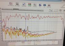
so you recommend me to do a square wave test to qualify my bass step up transformers
i´m using REW what settings should i put in to the spl Generator?
i can measure only Sound output dataset
also till know i could not find were i can measure like an ozilluskop is this possible with RWE?
Regards Paul
thank you for the link´s
the 2:nd ESL-attempt tread is very informative and present a handsome built
so you recommend me to do a square wave test to qualify my bass step up transformers
i´m using REW what settings should i put in to the spl Generator?
i can measure only Sound output dataset
also till know i could not find were i can measure like an ozilluskop is this possible with RWE?
Regards Paul
It may sound wrong, but smaller transformers have a higher primary inductance than larger transformers. A 5VA transformer has 10X the primary inductance of a 50VA transformer - so if you are worried about distortion due to core hysteresis, smaller is better.
regards
Rod
Hi,
There may be truth behind those arguments, but in practice every transformer is built different. In the past I have tested 25VA vs 50VA transformers from the same manufacturer. It has been built very similar but the core size. The small ones(at output, near max level) measured peak THD levels in the order of 0.1%. The larger, however, never exceeded 0.5% of harmonic distortion. As I have already posted, series resistance has a big impact on THD levels, assuming the source impedance(amp+wires) is low. due to this reason silicon based amp's will typically favor tube amps in terms of linearity.
Regards,
Lukas.
- Status
- Not open for further replies.
- Home
- Loudspeakers
- Planars & Exotics
- my first esl measurments questions