Hi,
I had build an ESl:
size 84cm * 38cm
each stator tow Transformer 230v/18V voltage amplification about 160
foil voltage about 5Kv
stator distance about 7mm
all is kept in low budget ~250€
During my measurements I had detect some strange behaves were I'm not sure were it comes from.
I guess it is the Transformer but maybe I'm wrong!
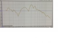
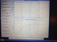
Can someone explain me were the waves are coming from (attached picture "original smoothing 1/6)?
the level of sound was going up and down
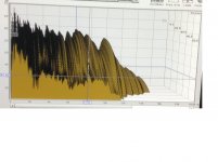
Also I'm wondering about the waterfall diagram! I can´t understand it is this a normal locking for a dipole measurement what was done inside a room? ( attached picture "wf" )
All measurements was done inside my living room
The ESL distance to the wall behind was about 1 m
The microphone distance was about 2 meters from the ESL
measurement software RWE
Microphone UMK1
The final result is locking ok but I believe there is a lot of improvement possible!
Best regards Paul
I had build an ESl:
size 84cm * 38cm
each stator tow Transformer 230v/18V voltage amplification about 160
foil voltage about 5Kv
stator distance about 7mm
all is kept in low budget ~250€
During my measurements I had detect some strange behaves were I'm not sure were it comes from.
I guess it is the Transformer but maybe I'm wrong!
Can someone explain me were the waves are coming from (attached picture "original smoothing 1/6)?
the level of sound was going up and down
Also I'm wondering about the waterfall diagram! I can´t understand it is this a normal locking for a dipole measurement what was done inside a room? ( attached picture "wf" )
All measurements was done inside my living room
The ESL distance to the wall behind was about 1 m
The microphone distance was about 2 meters from the ESL
measurement software RWE
Microphone UMK1
The final result is locking ok but I believe there is a lot of improvement possible!
Best regards Paul
Attachments

Hi,
it remains unclear what You´ve measured.
What are the differences in setup between the 1st and the 3rd graph??
To get the real behaviour You need a nearfield measurement in close proximity to the diaphragm <=10cm.
Your measurement system probabely allows for setting markers for a ´room-free´ measurement.
If not set properly the room response spoils the graph.
The velocity of sound in air is ~340m/sec.
From that You can calculate the wavelenghts, by simply dividing by frequency, or the Frequency, dividing by a distance or dimension.
With an 38cm wide, and close to double that value high, panel the free vibrating distance of the diaphragm will probabely be between 30-34cm (75-80cm), which coincides with ~1000Hz (~500Hz).
Standing waves on the diaphragm will show up at those frequencies and their multiples.
Also a measurement distance of 2m and a back wall distance of 1m coincide at frequencies of 340Hz and multiples.
So the chosen setup already must lead to a ´rough´ response graph.
Further remarks:
Two 230/18V trannies result in an U of 1:25, nowhere even close to a factor of 160.
If two trannies per stator -all in all 4pcs.- are used the factor will still be low 1:50.
This low factor may be used for a high capacitance panel of around 2nF.
Your´s is just around 380pF.
The impedance matching will be far off, Your Amplifier will see (too) high impedance.
If You use 4 trannies for a U of 1:50 the stator-stator distance should better be 2mm and not exceed 3mm.
This low distance requires supporting spacers to keep the free vibrating membrane distance lower than 100mm.
The Fs, the base resonance, will rise considerably, but the trannies are not useable for fullrange anyway, as isn´t the panel.
Frequency response is limited to above 200-250Hz only.
As is the efficiency of Your setup must be terribly low.
jauu
Calvin
moin,
the difference of diagram 1 and 3 is that i was using an equalizer to smoothen the response curve
the raw diagrame size is 84cm*38cm
how large should be the diagram at least to get a full range?
is there a easy rule / calculation to get the lower end freuenz
or does you mean transformers are basically not use able for full range?
in the end of this week i should come home then i will do a nearfield measurement.
yes you are right the efficiency is low 😀
what is my wrong thinking?
all in all i use 4 transformer (230v/18v)
example:
2V going in the first transformer 2v/18v*230v =25v
25v going in the second transformer 25v/18v*230v=319v
319v/2v =~160
this is my first built a lot of thinks i do not anderstand but time will teach.
i was built this speaker on an Weekend just to have a Feeling how it goes and how it sounds
if you like to have an endless deadly laugh i can upload my construction😀
thanks
Can you post a schematic of exactly how you have it wired?
They should be wired like this,
http://3.bp.blogspot.com/-G-ojgdj16zs/U4_Fia2CovI/AAAAAAAAA4k/SsA8ompBhtk/s1600/traids+10.bmp
From CharlieM's pages,
Jazzman's DIY Electrostatic Loudspeaker Page: The Electronics Package
If you have one transformer feeding another transformer this will not work good.
This will compound the add extra transformer capacitance's overall lowering the high frequency impedance to the amplifier to a very very low level.
Probably about 90% amplifiers power is wasted in the transformers capacitance and also since the impedance will be very very low the amplifier is not able to maintain the same voltage level at the higher end of the bandwidth.
Are you using Toroid type cores?
If so you can add your own primary as I have done here in order to bring your ratio up higher than the 1:25 you will get with them as they are.
http://www.diyaudio.com/forums/planars-exotics/161485-step-up-transformer-design-2.html#post2101604
This will save you from having to buy new transformers as there characteristics will not have changed if you get the very same size core but with a lower voltage LV winding.
The 230v HVwinding will be exactly the same for the new transformer as it would be for the one that you already have now for the same wattage size if it comes from the same company.
Are they from Antek?
Please DO, upload the pictures of your project as it will help us understand better of your setup.
You would be surprised at some of the creative configurations we have seen and still be able to get them to work!! 😀
FWIW
jer 🙂
Last edited:
hi,
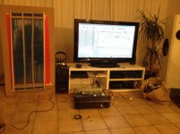
Attached you will find my schematic also my setup.
The picture is done last week with my mobilephone and i´m not at home so it is not in detail.
You can see currently it is only about function and not about a nice construction.
Thanks for feeding me with the transformer Information i Need to think about it the transformers i was using are very cheap 17€
Ringkern-Transformator 230 V~ 2 x 18 V 2 x 1.39 A 50 VA Sedlbauer im Conrad Online Shop | 518662
i have already order some Mylar 6µm
Ribbon Pleater for DIY Ribbon Loudspeaker Tweeter Artikel im music-in-life Shop bei eBay!
does someone know if this stuff is usefull??
cheers
Attachments

The ribbon pleater is of no use for esl's.
Are you trying to run them Full Range?
Full Range won't work with your current transformer setup, and still won't very well given their design.
You would have better luck getting two more of those cores and wire them for 18/960 at 1:51 ratio.
Even at this would be half of what you need unless you have a big amp than can produce a large voltage swing.
And what is your bias voltage?
You should have somewheres around 3Kv if not more too at least 6Kv in order to get a decent efficiency from them.
Your current setup shows to be only about 3.2Kv.
Here is a voltage multiplier calculator,
http://www.extremeelectronics.co.uk/calcs/index.php?page=cwvoltage.php
Every time you double the bias voltage you get 6db more efficiency but there is a practical limit typically of 5kv to 6kv or a little higher depending on the materials you used for construction and your stator to diaphragm spacing.
Having some supports to help keep your stator wires straight and with a even spacing to the diaphragm is a big plus and almost essential for proper operation and stability and should be considered.
It is great that you have them running otherwise!!! 😀
And getting a proper step-up transformer setup is what you need at this point in time.
Cheers!!!
jer 🙂
Last edited:
hi,
something was going wrong with the ebay link it should present 6µm Mylar Whatever...
😀 with calculator i get just 3,22 Kv nice link
i will go today to a shop und by some diodes and capacitors
in different words my bias voltage should be as high as possible and it will be limited by a ground leakage??
is it ok to use one bias supply for 2 panels?
regards
Yes, Use as high of a bias that is practical for you.
Once you start get up to and over about 8Kv it starts to become difficult to maintain it and keep it contained with in the system.
Ground leakage and stator to diaphragm arcing become the issue.
Not to mention internal arcing of the transformers.
I haven't had to much of an issue with this even at 10kv of bias, But panel leakage was my biggest factor to deal with.
In some earlier tests I was producing as much as 25Kv p-p out of the transformers that I have been using in the thread that I posted earlier.
However upon testing of one Antex AS-1206 I did have it fail at above 4.5 to 5.5KV coming out of a single unit.
I was able to repair it though.
It was an Electrostatically shielded type, So stay away from these types of transformers.
They are not suitable for this type of operation!!!
Beside the shield just adds more capacitance to the overall capacitance of the total parasitic (stray or self) capacitance of the transformer.
I have tested for this.
Using my high performance coatings I have been able to get as high as 10kv of bias in my in my .072" D/S gap but this was about the limit for the one set of panels that I made until they burned beyond repair.
However I did run them at 6.8Kv consistently to as high as 8 Kv or so.
The added efficiency was quite nice and this meant much less work for the amplifier!!
I was getting about +105db at 1 meter for such a little panel of 3.25"x9.75" just to give you an idea with just a 80watt amplifier.
I had about a 1:160 step-up ratio and they only required a 10v peak signal into the transformer to have +95db.
Normal listening did require anything more than a 5v peak signal and the amplifier liked this a lot.
This about the equivalent to a 1 watt level and my as measured efficiency was in the order of about 89-91db.
Your larger panel will have more efficiency than my little panels have due to the larger surface area.
Also have you considered doing a electrically segmented configuration of your stator, since you are using a stator made out of wire?
This will help with a few issues if you do,
First, It will provided for a lighter load for the amplifier at the highest frequency's.
This also will let you run a higher than normal step up ratio as well, this increases the overall efficiency as long as the impedance to your amplifier doesn't get out of hand.
Second, It will widen and even out the horizontal frequency dispersion so that you don't get the beaming effect at the higher end of the audio band.
This beaming starts to occur once the wavelength of the frequency being produced is equal to the width of the panels.
Typically at 1 to 4 octaves and above this is when it is really noticeable.
Third, This technique also automatically EQ's the panel to be flat as well, instead of having the normal 6db rising response caused from dipole cancellation.
Last but not least,
Yes, You can use the same bias supply to drive both panels.
I have a Friend that feeds both of his panels via 3 wires each from a single box that is the dedicated interface unit and it works very well.
Just remember that doing it this way can add to your overall capacitance from a long cable run depending on the type of wire you have and the insulation's dielectric factors, as well as the spacing of each wire to another one.
Still not exactly something that you would want to grab a hold of should you need to move it while the system is operating.
The voltages can in excess of 5kv to 15kv at full tilt and they are AC and will conduct through the insulation skin.
I have been nailed a few times from my own setup. He,he,he
IMHO Bias supply's are cheap to build and it may be safer in the long run to keep the interface close to the panel due to the voltages involved.
However it can be done, and it is your call.
I have found that it is best also (and a must) to feed each panel separately with its own series feed resistor to the diaphragm originating form the supply's output.
Or else the uneven leakage characteristics of each individual panel can/will cause issues of uneven distribution of the voltages and one panel may be louder than the other or not even play at all.
Also it is advisable to feed the each transformer's CT with through their own resistor as well on the other end of the supply as well ( but not necessary).
This will help with any possible crosstalk issues between the L&R that can occur as well.
It may be a very very small factor and not at all noticeable, but I have found that it does exist.
I have measured the voltages using my scope before and saw that the Bias voltage does get modulated a little bit from the voltages coming out of the transformers without using the resistors.
I have this info somewhere in these threads from about 4 years ago on this.
I found by just using 10meg to 30meg or so was enough to keep everything quiet and separated and nicely uniform depending on the leakage factor of the panels.
FWIW
jer 🙂
Thanks you so much for your Support!!!
You absolutely right there is no reason to have high voltage wires running in my rental
this is no sense
as i was listening musik and cleaning up my room the beaming effect was clearly indicated
I thought already about electrical segmentation
but i guess this might be too difficult to get an success
also to be honest i do absolutely not understand this
and so far i understand the beaming is in relation to the wavelength and not in general
it would be a dream if a ESL is constructable with an maximum and minimum beaming factor like´s example 0.3-0.4rad
or is this possible?
😀 and with my first prototyp is a wire segmentation not possible because it's just one 100m long wire coiled on the smaller wood frame 😀
one more question
what is the reason of an diagram segmentation??
you get a not so strong fs but several
isn't is better to have just one fs to get a clear cut off frequenz
or does i miss something??
regards
It would not be too difficult (maybe) to convert your panel as long as the ends are secured by a clamping system and /or glue so that the wires don't lose their tension.
Then it would be just a matter of snipping the loops to create the section's.
I used painted copper clad steel TIG rod for my latest design it is much more rigid and the rods are very straight and strong this way.
The stuff I used 1/16' dia. but thinner stuff is now available, But it wasn't when I bought my stock some 11 years ago.
But, you do have yours already built and this is a lot of the hard part already done!! 🙂
Here are the pages to my latest build, only I have yet to mount a diaphragm to it.
Other projects have been more pressing lately and I need to make a second one anyhow.
A Segmented Stator Desktop ESL
This is the reason I have been sticking with the smaller width sized panel as well.
When I made my very first panels back in 2003 one was about 8.5"x 21" and I made one exactly 1/4 the area (1/2 size).
And when I A&B them side by side I found that the littler 3.25"wide panel did not have this beaming effect.
At least no where as bad as the larger panel.
So I have stuck with that size ever since.
It wasn't until recently that I have figured out why this is. 😉
Physically segmenting the diaphragm works well to a certain extent, This is the method that most use.
However it has its limitation of the widths being set to one size, as electrical segmentation allows the driven area's width of the panel to vary with frequency.
This type segmentation also raises the resonate frequency of the diaphragm, this is okay if you panel is meant to be used in a hybrid system and is okay as long as your crossover frequency is kept at lest octave above this resonate frequency.
Then you have the issue of all of the sections with the same resonate frequency as well, again this is not much of an issue for the hybrid system.
But for full range many use a method of varying widths between the spacers to distribute the resonance's in a wider bandwidth rather than having them bunched up all at one frequency.
This has been under huge debate in a very recent and past threads, but commercial units have shown that this too does work and is quite logical.
Here are the links to a thread discussing a Calculator that is used for predicting electrical segmentation performance in my build.
http://www.diyaudio.com/forums/plan...tor-esl-simulator-esl_seg_ui.html#post2908293
And here is a version that was converted to english,
http://www.diyaudio.com/forums/plan...tor-esl-simulator-esl_seg_ui.html#post3192348
Later on in the thread the writer of this program was kind enough to post the script to this program as well.
There are many more programs and spreadsheets that I used to to predict the dispersion of my panel as well and I have them all listed in my pages at ESLdiy.
If you have any problem finding them or if the links are broken I can send them to you as well.
There are at least two more great threads on this subject here at DIYaudio too, But I don't have those links handy at this time but they may already be in my pages or in the calculator thread that I just posted.
Here is another link to a most excellent book and other information on this subject,
The Design of Electrostatic Loudspeakers - Frank Verwaal
Elektrostatic Loudspeakers
Cheers!!
jer 🙂
Hi,
Your idea of fixing and connection the wires is easy as brilliant "very nice"
The simulator is also a nice tool I was spent a lot of time on it😀
I just reach home and can't find my new diodes to increase bias voltage :/
I detect a new behavior on my esl during switch on bias voltage I hear some strange sound also during listening music
The complete foil was sticking on the wires shortly also some "klack" sound appears time after time
I think the foil has lose some tension or was tensioned to less in general!
If you build your ESL how you do you do the foile tension? How you know that you have the right tension??
Regards

Also I have measure the ground leakage
my calculated bias voltage is now about 9,66Kv
the bias voltage is running first a 25Kohn resistor and then to the foil
on the 25kohm resistor I was measure a dc voltage about 0,022V
0,022V/25000Ohm =0,00000088A
are 0,88µA a acceptable ground leakage?
Is it possible to calculate the real bias voltage?
Electro-metric or Electrostatic voltmeter. Electrostatic voltmeter - Wikipedia, the free encyclopedia.
It takes a bit of fiddling with the resistor values by the time you get a decent result.
The more sections you have the flatter you can get the off axis response.
Using many equal sections seems to work well for some, this way you only need one value of resistor for all of the sections.
I used a width doubling per whole section in my design and the simulation results were quite good.
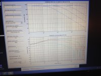
This is the reason I used 3,2,3,6 for just a 3.5" total width this tames the midrange bump you get in the simulation (see picture).
This cut down on the amount of resistors I needed for such a small panel with 25 rod sections.
Then I did a few simulations using this pattern with added wider sections of 12 and 24 for some much wider panels like yours and the results looked good as well
I also opted to omit the First resistor used to feed the panel at the center section.
This raises the on axis high frequency response slightly but helps flatten out the off axis response were I will be doing most of my listening in my setup.
Then I will also employ an active filter for tailoring this added brightness manually if needed.
This helps to keep the cost of the added resistors down and their power sizes down and the sensitivity up.
You can use LTspice or any other spice simulator to examine the power requirements of the resistors for your worst case scenario, I used Circuitmaker2000.
You can also build a very simple high voltage divider to accurately measure your bias voltage as I have explained in these threads,
http://www.diyaudio.com/forums/plan...as-voltage-sound-output-data.html#post4070779
A TEST JIG FOR FINDING ESL STEP-UP TRANSFORMER PARAMETERS
and here,
Does anyone have schematics of a varible HV power supply
I am not sure exactly how you are making you measurement with the 25k resistor but if it is correct your leakage looks pretty low and this is good.
I have not tried that method yet for fear of HV taking out my DMM but ohms law works!
My only question is the accuracy of a 25k resistor at a voltage potential in the KV range unless it is a resistor that is designed for use at such high voltages
Building a proper HV divider has been has been a priceless tool for me!!!
It was essential for when I designed my regulated variable HV supply.
Build it with as high of a resistance you can afford as they are quite cheap to make.
My last one only had a resistance of 20Megohm's, But that is because that is all of the resistors I had on hand at the time.
I had just enough to not exceed 500v per resistor with a 10KV input to the divider and I would have used more for a higher impedance if I had them.
Even at 20megohm's the supply has to be able to produce at least 5 watts of power to maintain 10KV.
This worked out okay considering it is only being used to measure the output of step up transformers.
So consider starting as high as 50Megohm range (2watts) if not at least higher to 100megohm's (1watt) or more.
The one in my supply was about 300mgohms,
http://www.diyaudio.com/forums/plan...tor-insulation-mylar-coating.html#post2780153
Use a Opamp buffer to isolate your meters input resistance from the divider as well.
I can't stress this enough unless you can except the inaccuracy's and/or don't mind calculating the error manually.
I use this calculator for such use,
Voltage Divider
Here too is an excellent calculator for determining your power supply's performance,
Cockcroft walton Voltage Multiplier Calculator
Adding a current measurement system to my supply is next on my list as well as a digital voltage control, even though it is very accurate and doesn't drift as is should you decide someday to approach such a design.
I do use it a lot for testing of materials at times as well as powering my ESL's.
I really need to build the new improved version I have in mind!! 😉
I also have I more DIY'er Friendlier version of a variable regulated HV supply that I have been meaning to present as well, once time permits for me to get it done.
Cheers!!!
P.S. You have your Stator Height set a 2 meters, Is this correct?
In your first post you said it was 84cm, or is this a new design?
jer 🙂
The more sections you have the flatter you can get the off axis response.
Using many equal sections seems to work well for some, this way you only need one value of resistor for all of the sections.
I used a width doubling per whole section in my design and the simulation results were quite good.
This is the reason I used 3,2,3,6 for just a 3.5" total width this tames the midrange bump you get in the simulation (see picture).
This cut down on the amount of resistors I needed for such a small panel with 25 rod sections.
Then I did a few simulations using this pattern with added wider sections of 12 and 24 for some much wider panels like yours and the results looked good as well
I also opted to omit the First resistor used to feed the panel at the center section.
This raises the on axis high frequency response slightly but helps flatten out the off axis response were I will be doing most of my listening in my setup.
Then I will also employ an active filter for tailoring this added brightness manually if needed.
This helps to keep the cost of the added resistors down and their power sizes down and the sensitivity up.
You can use LTspice or any other spice simulator to examine the power requirements of the resistors for your worst case scenario, I used Circuitmaker2000.
You can also build a very simple high voltage divider to accurately measure your bias voltage as I have explained in these threads,
http://www.diyaudio.com/forums/plan...as-voltage-sound-output-data.html#post4070779
A TEST JIG FOR FINDING ESL STEP-UP TRANSFORMER PARAMETERS
and here,
Does anyone have schematics of a varible HV power supply
I am not sure exactly how you are making you measurement with the 25k resistor but if it is correct your leakage looks pretty low and this is good.
I have not tried that method yet for fear of HV taking out my DMM but ohms law works!
My only question is the accuracy of a 25k resistor at a voltage potential in the KV range unless it is a resistor that is designed for use at such high voltages
Building a proper HV divider has been has been a priceless tool for me!!!
It was essential for when I designed my regulated variable HV supply.
Build it with as high of a resistance you can afford as they are quite cheap to make.
My last one only had a resistance of 20Megohm's, But that is because that is all of the resistors I had on hand at the time.
I had just enough to not exceed 500v per resistor with a 10KV input to the divider and I would have used more for a higher impedance if I had them.
Even at 20megohm's the supply has to be able to produce at least 5 watts of power to maintain 10KV.
This worked out okay considering it is only being used to measure the output of step up transformers.
So consider starting as high as 50Megohm range (2watts) if not at least higher to 100megohm's (1watt) or more.
The one in my supply was about 300mgohms,
http://www.diyaudio.com/forums/plan...tor-insulation-mylar-coating.html#post2780153
Use a Opamp buffer to isolate your meters input resistance from the divider as well.
I can't stress this enough unless you can except the inaccuracy's and/or don't mind calculating the error manually.
I use this calculator for such use,
Voltage Divider
Here too is an excellent calculator for determining your power supply's performance,
Cockcroft walton Voltage Multiplier Calculator
Adding a current measurement system to my supply is next on my list as well as a digital voltage control, even though it is very accurate and doesn't drift as is should you decide someday to approach such a design.
I do use it a lot for testing of materials at times as well as powering my ESL's.
I really need to build the new improved version I have in mind!! 😉
I also have I more DIY'er Friendlier version of a variable regulated HV supply that I have been meaning to present as well, once time permits for me to get it done.
Cheers!!!
P.S. You have your Stator Height set a 2 meters, Is this correct?
In your first post you said it was 84cm, or is this a new design?
jer 🙂
Attachments

Last edited:
Hi,
yes a new construction will be done😉
the foil is already ordered and it is sticking at customs i can pick it up tomorrow.
Also i have decided how wide and tall i will build it ( attached Picture)
how you think about that?
i will build it again with wires and there i got some question:
which Kind of wires are recommended?
in my first built i have used H07V-U 1,5mm² and i was not that successful with it i guess it is to stiff to tension it 100% flat and to soft to be like a tube
how about woven wires?
is there a simple trick how to get it super straight?
best regards Paul
Attachments
Hi,
the number of wires per width in #12 is way too low to achieve a devcent efficiency.
Increase the number of wires so that You get 30-50% of open area.
The H07-VU is the wire Acoustat used.
You may orientate on their design, apart from the ridicolously high stator-stator distance.
With H07-VU the free distance between assisting supports may bridge 10-15cm.
To straighten the ires there seem to be two possibilities.
The first is to build a stretching jig where all the wires are wound onto and where all wires are stretched once at the same.
This method requires to stretch the wires to a point where the copper starts to 'flow'.
The flow conditions is marked by a sudden reduction in required pulling force and a associated thinning in wire diameter.
Unfortunately the point of cracking the wire is not far and depends on the quality and treatment of the wire.
The wire should have had a proper heat treatment from the manufacturer.
If You go for a thinner wire, like H07's small brother, the H05-VU, the probability of cracking rises.
Find a good manufacturer of a accordingly treated wire, even if it costs a bit more.
Both wire types are PVC insulated which is not only good suited as insulation material for this application, but is also very common and cheap.
Kynar insulated wirewrap wires (silver plated copper) offer slight advantages on paper, but are costier and may give issues fixing the wires to a support structure.
The second method requires much more work and time, but guarantees perfectly straight wires without the need for a stretching jig.
Here You stretch every single wire.
Cut the wires to length plus a few cm of reserve.
Fix one end solidly and the second end in a drilling machine.
Pulling the wire and turning the machine back and forth at the same the wire is stretched.
There will come a clear defined point (the flow point) where the vibrating wire suddenly stops vibrating and the pulling force reduces.
The wire is then stretched perfectly straigt.
I checked that with a very slightly tilted glass plate on which the wire had to roll off from.
A stretching method rather suited to thicker wires and for very patient minds.
You can see pics of the results on my website.
jauu
Calvin
Hi,
😡 a lengthy comment about the sim paras went into the off 😡
just in short.
The chosen sim params are not very practical.
2m height: alot mire than required and sensible, esecially for a hybrid panel.
Width and number of segments: too thin, too many. 2-3 electrical segments suffice, for example 3cm + 2x6cm + 2x12cm.
d/s of 3mm: criticically much for reasonable efficiency.
bias voltage: way too high. 3-5kV will be the maximum You could achieve as true bias in the airgap. You can't use the figures of the supply's output voltage here.
The sim sims unrealistic high nearfield Spl values.
On distance the sim results look plausible for the chosen impractical simulation values.
It seems You want to try to test Your skills and patience on a fullrange project. Why?
Problems just rise with every Hz below 150Hz and all important parameters deteriorate. Chances for success are alot better for a hybrid design.
You know that You can't use the simple power toroids for fullrange useage?
jauu
Calvin
Hi,
I have done some test🙂
Once i tension the wire till it brocken
And once with a driller
!!!Driller is Perfect!!!
This is how i will do it ( picture )
You make me thinking about the Konstruktion
I have read the manual or instruction which was linked a vew post bevor ( thanks by the way)
The core saturation is the issue...
If I would build a hybrid were the subwoofer/ bass is going up to ~150hz
Which size is recommended for the panele??
With a hybrid does I have some disadvantages by using cheap ring transformers 230v/6v?
Cheers
- Status
- Not open for further replies.
- Home
- Loudspeakers
- Planars & Exotics
- my first esl measurments questions