Typically for a Hybrid setup up I would suggests a panel width of 6" to 8" with 10" to 12" being an absolute maximum!!
After 8 Inch's you could start to run in to stability issues with the diaphragm and also have problems getting enough tension on it.
Getting to 150hz with your typical Toriod Transformer setup is possible at a lower level at about 18v input to the transformer.
If you have a large amplifier that has a bit of voltage swing to it you can except to only get down to 300Hz to 360Hz before the core will start to saturate.
Also your load impedance will be very very low for the amplifier in such a low frequency range as well due to the primary's low inductance.
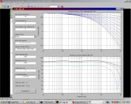
Take a look at the tests I did for just one Antek AS(AN)-1206 that I did here,
http://www.diyaudio.com/forums/planars-exotics/233008-esl-hybrid.html#post3434477
Notice the Impedance charts I did for this very same transformer here,
http://www.diyaudio.com/forums/planars-exotics/161485-step-up-transformer-design-6.html#post3404300
This is just for one core that is unloaded and the impedance you see will be half of that for two cores with their primaries connected in parallel as in a normal setup.
This is typical for most any core of this type with a 6V winding used for the primary, But, Not exact for all cores, but typical to give you an idea.
As I had mentioned before, Stay Away from the shielded types (AS-xxxx from Antek)!!!
FWIW
jer 🙂
After 8 Inch's you could start to run in to stability issues with the diaphragm and also have problems getting enough tension on it.
Getting to 150hz with your typical Toriod Transformer setup is possible at a lower level at about 18v input to the transformer.
If you have a large amplifier that has a bit of voltage swing to it you can except to only get down to 300Hz to 360Hz before the core will start to saturate.
Also your load impedance will be very very low for the amplifier in such a low frequency range as well due to the primary's low inductance.
Take a look at the tests I did for just one Antek AS(AN)-1206 that I did here,
http://www.diyaudio.com/forums/planars-exotics/233008-esl-hybrid.html#post3434477
Notice the Impedance charts I did for this very same transformer here,
http://www.diyaudio.com/forums/planars-exotics/161485-step-up-transformer-design-6.html#post3404300
This is just for one core that is unloaded and the impedance you see will be half of that for two cores with their primaries connected in parallel as in a normal setup.
This is typical for most any core of this type with a 6V winding used for the primary, But, Not exact for all cores, but typical to give you an idea.
As I had mentioned before, Stay Away from the shielded types (AS-xxxx from Antek)!!!
FWIW
jer 🙂
Hi,
I rethink about construction and now I will go for hybride 🙂
15cm wide and 150cm tall the foil will get stability every30cm
Is there a basic rule about d/s spacing
Example:
1. D/s 2 mil and bias voltage 3000kv
2. D/s 3 mil and bias voltage 6000kv
Theoretical I should resive almost the same output level
But will be there a different in sound?
I mean the quality of sound and not if it be perfect values
I hope you know wath I mean 🙂
Regards
Hi,
the panel will be of a size that needs intermediate supports or spacers.
So if its needed anyway, go for a wider panel.
You need to keep in mind, that acoustic phase cancellation starts the higher in frequency the thinner the panel builds.
To counter that effect it requires either ´fins´ as passive Baffle extensions to the left and right of the panel, or more electronic equalization.
You certainly don´t need so much height, but more width.
My small panel measures 25x125cm and here phase cancellation starts as high as ~600Hz.
Its crossed over at ~250Hz.
The bigger panel measures 40x150cm, crossed over at ~180Hz.
Making the panel wider -i.e. making the active membrane larger- is better than adding a ´passive´ Baffle to a smaller panel, sonically as well as optically.
More membrane area allows for less excusion, which is good for efficiency, which itself is the most important design parameter.
Keep d/s as small as possible. My panels use a d/s less than 1.5mm.
As a rule of thumb the free vibrating distance between two spacers/supports should not exceed 70-100 times the d/s.
Less than 70x costs on efficiency, more than 100x risks the diaphragm collapsing into a stator.
jauu
Calvin
ps: mil means 25/1000mm , so if You talk about the metric Millimeter it´d be smarter to use the mm abbreviation and not the imperial mils. 😉
Last edited:
Hihi upsi 🙂
If the surface of the panel is around 0,5m2
the excursion should be around 0,1mm to get ~110dB calculated without phase cancellation😉
For hybrid speaker:
I'm right if I saying to design a panel the foil excursion can be ignored??
Is it also right that the only problem with small d/s are diagram collapsing if the stators are perfect isolated??
The H07V wire has if I remember me correctly a isolation about ~0.5mm
So spacers of 1mm would you recommend me??
Regards
Roger Sanders originally Expressed a ratio about 1:100 for a D/S to Width.
I have found that I prefer about a 1:75 to 1:50.
Foil excursion should not be ignored depending on the lowest frequency you are trying to produce.
In order to maintain the same SPL of each lower octave the excursion goes up 4 times!
I Suggest going above 3mm D/S doesn't have any practical advantages for most unless it was meant only for bass.
At this point bass signals don't fair well due to lack of diaphragm control at such high excursions and the voltage and transformer requirements are at an extreme for this type of operation.
For anything more than that I have been wanting to try some compounded diaphragms strictly for bass use as well as using a HV servo amp design.
I have been able to manually control the position of a diaphragm quite nicely with my variable supply as it is the transformer that is the limiting factor for the lowest end of the audio range.
Even 2mm D/S seems to be ample for most of my experiments down to 200hz with my 3.25" panels.
My as measured D/S was about .072' to .075" on those.
I have also calculated this 1.85mm d/s into my latest build as well, But I can also increase this at any time just by adding some spacers.
This is something I wish to explore with greater detail now that I have made some stator's that are able to handle the extreme voltages that I was using when I burned up my last set.
When I drove those to diaphragms into stator clipping they were extremely loud for such a small panel at even 200Hz to 300hz.
I like it loud but it was actually to loud for me at the time (+110db) although I didn't have a working SPL meter at the time they blew up.
By increasing the D/S on those to around .085" to .093" or so, I never got them to clip before I ran out of driving power below 200hz.
Except when I approached their resonate frequency at 70hz to 90Hz, This did cause some issues as expected.
After about 20minute of such abuse is when they finally failed and exploded into flames from coating failure at about 25Kv p-p across the stators.
At about 15Kv p-p or so at half (-3db to-6db less SPL but loud enough that I could clearly hear them downstairs) they ran for hours on end.
I had about 6Kv or more of bias on them too as this was before I had finished my regulated HV supply and was able to get an exact voltage reading of the voltage.
Actually, It was a sharp point that was not properly insulated that caused the failure since my stator material of choice is aluminium wire mesh (window screen).
My First set of ESL's were 8" x 22" panels and I had two sizes for spacers to choose from, as with all of my designs so far including the smaller ones, 1/16" (.062") and 3/32 (.093").
Plus about .010" to .015' added to that for some construction offset due to the design and materials I used.
First, Using the 1/16" spacers, They worked quite nicely, But I was having some slapping on the lowest frequency's 40Hz to 60Hz.
This is most likely probably due to their resonate frequency as at the time I didn't have the tools and ability to measure all of this then as I have done now with my little panels.
Also due to their width and 4x size (surface area) compared to the little panel of course they produced a stronger low end.
This is when I discovered that using the 3/32' spacer took care of any diaphragm to slapping issues that I had for those panels and that an increase of Bias Voltage took care of any inefficiency issues the thicker spacers caused.
I made them so that I could swap out the different thickness frames and spacers at anytime and I did this a lot for comparison testing.
I was able to do this for both 8" and 3.25" wide panels back in 2003.
This is also when I found that I favored the smaller width panels as well due to their dispersion quality's.
The SQ was the same as well only the wider panels had an more extended low range as expected.
There was no difference in the way the two sets sounded as far as coloration of the midrange as there was none.
Knowing that I was going to use a woofer anyhow I overlook this inability and have stuck with building the smaller size's ever since.
I got back into in 2010 when I found out about Calvin and CharlieM using some Power Toroid's as step up transformers and got them out of the closet and started testing stuff again.
This led me to building my variable Bias supply so that I could verify the 6db increase of sensitivity for every doubling of the bias voltage for myself.
When I First started I was hard pressed to get any kind of sound out of them at all and my 900v bias supply just wasn't enough!!!
Voltage means everything for these things to work and now I have taken those exact very same panels I made in 2003 that were hardly enough to be used for headphones to the point of taking you out of the room with loudness to spare!!!
For the low end you need displacement but the drawback is you need lots of voltage to Produce bass, but there is a practical limit due to the materials used.
ESL's don't use any power to produce bass either, but the issues is how do you control such high voltages.
Well, it can be done but that is beyond the scope of this topic for now.
Cheers!!
jer 😉
I just stumbled on this small discussion on spacer thickness,
http://www.diyaudio.com/forums/planars-exotics/109789-esl-diaphragm-coating-7.html#post2082811
And the verification of my findings with my llittle panel here,
http://www.diyaudio.com/forums/planars-exotics/109789-esl-diaphragm-coating-7.html#post2082937
and here,
http://www.diyaudio.com/forums/planars-exotics/109789-esl-diaphragm-coating-7.html#post2084272
jer 🙂
Hi,
i head read you links
i guess i will do some test about very low d/s.
The Isolation at the H0V-U wire is 0,45mm.
If i build a Panel with a airgape about 0,2mm then i will reach a d/s 0,75mm waht will garantie me a high effectivity.
the wires are isolated so i dont should get any arcing only the foil collapsing could be an disadvantage were the limiting factor is "only" the bias voltage and foil Tension.
Right?
also i do a calculation (Strassacker, Komponenten: Lautsprecher, Frequenzweichen, Bauelemente)
tow panels 1,3m tall and 40cm wide will have a excursion about 0,04mm to
reach 100Hz at 100dB in reality it will be absolutly less maybe more then the half but this will be for me ok i dont need it noisy. At 150hz what will be
the target cut off frequency it will be 0.02mm also for 100dB.
way usually People going to build Panels with large d/s?
i cant see any real Advantages ( Special for hybride)
does i have any large Information leaking?
i mean technical and not my rubbish writing hihi
best regards Paul
Last edited:
Hi,
with the H07-VU wire I would opt for min. 1.5-2mm d/s.
For lower d/s values I´d opt for thinner wire, for example the H05-VU.
But as You like to reach down to 150Hz and since this is Your first project, I suggest to use the above mentioned 1.5-2mm d/s.
This will give You decent efficiency, and allows for enough room for the membrane to move and to apply high Bias voltage.
If You build the panel Audiostatic-like, a 3.5mm thick spacer frame and H07VU wire will result in a d/s of 1.7mm.
Add 1/10mm for the glue joint and You end up at ~1.8mm d/s.
Stretching the diaphragm quite hard and placing additional spacer dots You can end up with a base resonance around 100Hz, which is as closest possible to 150Hz xover if notched properly.
You may be able to bias the diaphragm between 3-5kV.
The audio tranny then may have an U of 1:70 - 1:120 with proper electrical segmentation.
juu
Calvin
Hi,
Building is in process...
The panel will have a size about 120cm tall and 50cm wide
The frame is already done. A easy steal construction.
About the spacing I'm still not sure but I guess I will do 1,5mm
Pictures I will link up soon I'm actually on a business Tripp....
I was order some Mylar foil and this is already arrived inclusive there was 60g elvamide!
The shipping was started from China (eBay seller)
Does someone know if this stuff is usefull??
I have read a coating aply Instruktion but i cant find any Advanced Information.
How much grams i have to aply per cm2??
Methanol I have already It was not so easy to get it every pharmacy was owne a 1L bottle but they won't sell it know I know every pharmacy in my location😀
Best regards Paul

Very Nice!!!
I would consider a D/S in the the 2mm to 3mm range for your chosen width unless you are planning on crossing them over at a higher infrequency like 400Hz to 800hz range.
Since an ESl has a rising frequency response (even though it is compensated by filtering or electrical segmentation) your lowest frequency operation vs SPL will set the bar for your overall flat response and listening level.
Even though you may not listen to them loud you must also consider the drop in SPL the farther away you get from them.
For instance in my room of 18' feet long I get a drop of nearly 10db from the speaker once the sound reached my listen area.
This is the reason why I stress High SPL's all of the time, not just because I do like them loud at times. 😉
But because they have a considerable distance from me as well.
My living room is a bit larger at 24' and I have to keep this in consideration when I finally make a set for that area.
Here are few discussion on this matter,
http://www.diyaudio.com/forums/plan...-panel-size-vs-sound-quality.html#post3783205
http://www.diyaudio.com/forums/planars-exotics/246846-first-time-esl-builder.html#post3733046
This post has the links to some more discussions and great spreadsheets to help you with such considerations,
http://www.diyaudio.com/forums/planars-exotics/246846-first-time-esl-builder.html#post3734281
Here are the Spread sheets, I think there are two versions,
v1,
http://www.diyaudio.com/forums/planars-exotics/48120-experiences-esl-directivity-2.html#post2204784
v2,
http://www.diyaudio.com/forums/planars-exotics/48120-experiences-esl-directivity-2.html#post2218526
Yes,
In my earliest models I used to coat both sides of the diaphragm and I only found by ear maybe a .5db to 1db difference in the efficiency if that as it was not scientifically measured at that point.
I really had to struggle to find any difference at all in the level between a single sided coating or a dual sided coating.
So since then I save on my coating material and stick with the single sided method.
Also as you mentioned I did have issue with a few that were double coated, and when one side was not connected it caused it to charge in the opposite polarity as the other side or if it was not making a proper connection.
Sometimes this was enough to neutralize the effect of the Bias Voltage and cause a diminished efficiency and sometimes render no sound output at all out of the panel.
Even though I could prove that there was actually bias applied to one side of the diaphragm.
This was a shocking discovery....Trust me !!! 😉
Reconnecting the other side would normally restore the sound!!
Sometimes I ran into situations where I could not get them to work at all and then after taking them apart and reassembling them they would work again and maybe sometimes fade out again.
There could have been other factors involved but I never really nailed it down to just one thing as it was just a few of my very first attempt's did I have such issues.
After that I stuck with single sided coatings.
jer 🙂
Last edited:
Hi,
provided that You electrically equalize the panel well enough and build with high precision, 1.5mm d/s may suffice for x-over frequencies >180Hz.
For 150Hz I´d choose 2mm.
As first build You may want a bit of safety margin, add 2/10 to 3/10mm to that value.
Stretch the membrane very hard and apply for additional spacers so that the base resonance of the panel settles at >>100Hz.
If You plan on a high efficiency ESL xover not lower than 150Hz.
For Your panel size I´d rather opt for ~200Hz.
As gerald already pointed out, is double sided coating a source of trouble and of no measurable use.
Btw. a few of my earliest panels didn´t want to leave the listening room at all to be shown around.
They simply stopped working each and every time I wanted to show them elsewhere and resumed perfect conditions when reinstalled at home.
Since then I´m convinced that they are no dead matter but creatures with their own divaesque and sometimes truely bitchy personality. 😉
So, never say die! 😀
jauu
Calvin
Hi,
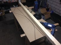
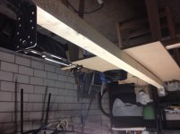
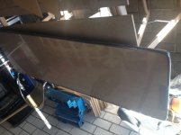
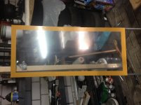
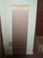
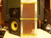
I have detected a Problem my Frame is not stiff enough
you can see it at Picture post 34
my Frame what should look like a square but now it is more like a sand clock.
so i get unequal foil Tension...
i was hoping to get the "invisible view" with the slim steel Frame
someone some experience with plexiglass??
regards Paul
All of my frames are made from Plexiglass.
There is a lot of force from a piece of tensioned mylar!!
Even if you only are using heat to tension it.
On my plastic lighting grate stator support models, The tension was high enough to make them bow out away from the diaphragm a bit by as much as .020" or so somay be a little more on my 8.5" wide version.
This did cause some issues of getting enough tension at First.
But once I did get enough they worked just fine even though they were slightly bowed.
I was still able to repeatably take them apart and re-assembled over and over without having to retention them anymore than they already were.
Since the Diaphragm frames are quite flimsy by themselves you need some type of heavier material around the perimeter as well to sandwich them in.
My frames were only about 5/8" wide but for as a large width as you are purposing I would no less then about 1.5" to 2".
I think you could get by with only 1" wide frames as well as long as you are able to sandwich them properly with out them slipping.
I used bolts to mount them every 4" or so.
For a panel your size this would mean A Lot of them and it can be very tedious should you decide/need to take them a part a few times.
Bolts work very well, but they are a small investment (mostly time) and don't bother with any of the plastic or Nylon types as the are to costly for the larger gauges as the smaller ones (#6's & #8's) just strip out and lose their ability to hold their tension.
These problems are a lot of the reasons I built my latest version using a rigid steel wire stator that is painted.
The new panel has no flex to it at all and the acrylic paint has 3 to 5 times the dielectric strength PVC coated wire has.
I would have used a .035" or .045" wire (TIG Rod) but I only have some 1/16" on hand at the moment.
By the time I added the coating, The final diameter is about .078" to no more than .080".
With a coating thickness of only 8mil (.008") each stator withstands a 14KV test with no punch through!!
I have made some larger 11"x36" stators but I have not coated them yet.
Since they are not segmented I haven't decided what to do with them yet, either cut them in segments or just leave them whole for some bass only panel design.
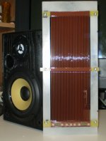
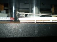
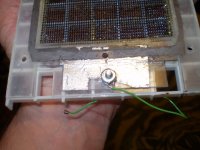
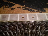
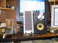
Here are a few pictures that may give you some idea's.
The one that shows the graphite charge ring is one half of the diaphragm frames laying on one of the stator frames.
I still a couple of full pieces of the plastic grating and I was thinking about using it for some bigger panels as well for just the perimeter as it really quite strong enough once it is boxed in even on just one side and them mount that to a wood frame or something.
The TIG Rod stators are very stiff and the plastic grate perimeter would work great with them.
The last picture I just now found, I wanted to post it before as it shows what the simulator predicted should I have chosen to segment every rod on my small panel using all 10meg and 15meg resistors I think, except for the First one.
jer 🙂
There is a lot of force from a piece of tensioned mylar!!
Even if you only are using heat to tension it.
On my plastic lighting grate stator support models, The tension was high enough to make them bow out away from the diaphragm a bit by as much as .020" or so somay be a little more on my 8.5" wide version.
This did cause some issues of getting enough tension at First.
But once I did get enough they worked just fine even though they were slightly bowed.
I was still able to repeatably take them apart and re-assembled over and over without having to retention them anymore than they already were.
Since the Diaphragm frames are quite flimsy by themselves you need some type of heavier material around the perimeter as well to sandwich them in.
My frames were only about 5/8" wide but for as a large width as you are purposing I would no less then about 1.5" to 2".
I think you could get by with only 1" wide frames as well as long as you are able to sandwich them properly with out them slipping.
I used bolts to mount them every 4" or so.
For a panel your size this would mean A Lot of them and it can be very tedious should you decide/need to take them a part a few times.
Bolts work very well, but they are a small investment (mostly time) and don't bother with any of the plastic or Nylon types as the are to costly for the larger gauges as the smaller ones (#6's & #8's) just strip out and lose their ability to hold their tension.
These problems are a lot of the reasons I built my latest version using a rigid steel wire stator that is painted.
The new panel has no flex to it at all and the acrylic paint has 3 to 5 times the dielectric strength PVC coated wire has.
I would have used a .035" or .045" wire (TIG Rod) but I only have some 1/16" on hand at the moment.
By the time I added the coating, The final diameter is about .078" to no more than .080".
With a coating thickness of only 8mil (.008") each stator withstands a 14KV test with no punch through!!
I have made some larger 11"x36" stators but I have not coated them yet.
Since they are not segmented I haven't decided what to do with them yet, either cut them in segments or just leave them whole for some bass only panel design.
Here are a few pictures that may give you some idea's.
The one that shows the graphite charge ring is one half of the diaphragm frames laying on one of the stator frames.
I still a couple of full pieces of the plastic grating and I was thinking about using it for some bigger panels as well for just the perimeter as it really quite strong enough once it is boxed in even on just one side and them mount that to a wood frame or something.
The TIG Rod stators are very stiff and the plastic grate perimeter would work great with them.
The last picture I just now found, I wanted to post it before as it shows what the simulator predicted should I have chosen to segment every rod on my small panel using all 10meg and 15meg resistors I think, except for the First one.
jer 🙂
Attachments
-
 Ready for The Diaphragm.jpg168.3 KB · Views: 100
 -
 Stator3.jpg547.3 KB · Views: 87
 -
 Graphite charge ring.jpg574.2 KB · Views: 98
 -
 ESL4.jpg142.9 KB · Views: 91
 -
 ONE TIG STATOR a.jpg185.6 KB · Views: 95
 -
 ESL3.jpg60.4 KB · Views: 88
 -
 ESL1.jpg99.2 KB · Views: 132
 -
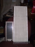 Big vs Small.jpg59.2 KB · Views: 147
 -
 Segmented diaphragm.jpg257.4 KB · Views: 92
I did a deliberate test once of over shrinking the diaphragm when it was just on one of the frames and not mounted for any added support and it snapped it!!!
Right in half, and, not at the section where they were glued together either!!!!
I wasn't using .25mil Mylar at the time but it was some sort of PET film.
I was using a model airplane covering called UltraKote, it is the thinnest stuff I could find as it is about .6mil to .75mil.
I wanted to see how much it would actually shrink if I let it, and it did, enough to snap the frames!!
Tensilized Mylar will not shrink that much but will shrink enough to make impossible to get them back together if you are not careful!
Just to give you an idea of just how much force there is once they are tensioned.
A couple of times I really had to really fight hard to get them back together again, as the bolt holes were off by as much of 1/16" in the middle of the long part of the frame, and, even more on a few Diaphragms I had mounted that I had shrunk a bit to much.
One time I broke a set of frames and had to glue them back together and start with a new diaphragm as well.
FWIW
jer 🙂
Hi,
I assume that the frame from #34 is only for tensioning the membrane temporarly?
You may try to press in two or three additional braces to get it sufficiently straight again.
At first most people underestimate the strength of those thin films and how much force they can take, resp. exhibit.
It gives a hint though how strong the final stator frame needs to be and how much area the glue joint between frame and film requires.
A rectangular shaped frame made of spacer material requires bracing every couple of cm to remain in shape, either in form of plastic light crates or discrete rods like Audiostatic used.
To avoid situations as Yours I can only suggest that You post Your full concept and ideas of mounting here, so that we can help You avoid running into issues like the ones above.
jaa
Calvin
- Status
- Not open for further replies.
- Home
- Loudspeakers
- Planars & Exotics
- my first esl measurments questions