Hi all!
It has ben many years since my last post here, I guess some 20 years, I am now retired an have some more time to my Hobby.
I am working on this CFP, which causes me som troubles.
I would be wery thankful if any of you could give me a hint to solve my little problem.
I have attached files to give you an idea of my project.
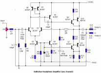
Micro-Cap schematic:

Kicad schematic:

KiCad pcb

KiCad 3D

Pcb under test

Test setup:

Here is the problem:
1. When I power up the amp without speaker connected all is fine and dc off set at the output terminals is 70mV. After powering up I can connect the speaker and hear some music.
2. Powering up with the speaker connetcted causes the amp to draw a lot of current, and I have 6V on the terminals.
3. Powering up with a cap in series with the speaker, all is fine and I have music in the speaker.
4. Powering up with an 120 ohm resistor in series with the speaker also does the trick, with les music volume of cause.
I really would appreciate som help, please!
Henrik
It has ben many years since my last post here, I guess some 20 years, I am now retired an have some more time to my Hobby.
I am working on this CFP, which causes me som troubles.
I would be wery thankful if any of you could give me a hint to solve my little problem.
I have attached files to give you an idea of my project.
Micro-Cap schematic:
Kicad schematic:
KiCad pcb
KiCad 3D
Pcb under test
Test setup:
Here is the problem:
1. When I power up the amp without speaker connected all is fine and dc off set at the output terminals is 70mV. After powering up I can connect the speaker and hear some music.
2. Powering up with the speaker connetcted causes the amp to draw a lot of current, and I have 6V on the terminals.
3. Powering up with a cap in series with the speaker, all is fine and I have music in the speaker.
4. Powering up with an 120 ohm resistor in series with the speaker also does the trick, with les music volume of cause.
I really would appreciate som help, please!
Henrik
Last edited:
Hi Henrik,
I'm afraid I don't have any obvious insight.
Can you test with a suitable load so that you can provoke the problem but not put your speakers at risk?
Item 2 in the list: when the amp latches-up with 6V on speaker terminals, what voltages appear on the supply rails?
Item 3: what is cap size and resistance of load in this experiment?
Would you provide a schematic of your power supply? It appears you have resistors is series with B+ an B- supply leads. Would you explain their intent/function and value?
Thanks and good luck!
Steve
Where is everybody? Out watching holiday lights?
Drive of Q10 is decidedly weird.
Normally emitter of temperature sense transistor Q4 would drive base of Q10 through some resistance. You've got some kind of CCS or dc voltage driving Q10? Q4 driving base of Q11 the driver makes some sense, but what is Q10 for? I don't know what cfp means, but this is by no means a leach amp. Normally Q1 the VAS drives both drivers through a voltage spreader, either stack of diodes or a VBE multiplier like Q4.
Q4 doesn't seem to be located to sense the temperature of the heat sink attached to output transistors Q2 Q12. The output transistors don't seem to be located to mount on an external heat sink. How much wattage you want, 2?
BTW electrolytic speaker caps for split supply amps sound weird at low wattage in my experiment. Split supply amps the speaker returns to the middle. Top octave piano didn't sound right with back to back 6800 uf polar caps series the speaker. You can't afford a 3300 uf film cap that can go + or - without slow chemical events. A 330 uf 100 v film cap is about $20. Speaker caps are fine for single supply amps with the speaker connected to the negative rail. Then an electrolytic cap is positively biased at all times.
I don't save schematics of split supply amps, but if you are looking for something that works, Apex has some. The AX14 80w looks similar to your board but actually has worked. He has sophisticated dc feedback from the speaker cap input on the AX6 I have built. More complicated commercial amps use an op amp to act as "dc servo" to keep speaker hot from wandering off zero in the middle. This usually connects to Q3 the feedback transistor.
Last edited:

Hi Steve
I am also using a dummy load.
I haven't noted the exact psu voltage when I have 6V on the terminals, but I guess it is close to 6V.
I am using a test supply regulated with LM317/337 at 20V.
The load is 8 ohm and the cap size is a bipolar at 4700uF.
I have two 1 ohm resistors in series with + an - at the PSU, I measure the current as a voltage drop across them.
The PSU that I will use for the amp is a simle one, a left over from a Gainclone:

Thanks for the good luck!
Henrik
I am also using a dummy load.
I haven't noted the exact psu voltage when I have 6V on the terminals, but I guess it is close to 6V.
I am using a test supply regulated with LM317/337 at 20V.
The load is 8 ohm and the cap size is a bipolar at 4700uF.
I have two 1 ohm resistors in series with + an - at the PSU, I measure the current as a voltage drop across them.
The PSU that I will use for the amp is a simle one, a left over from a Gainclone:
Thanks for the good luck!
Henrik
Hej indianajo
Thanks for your words.
Where is everybody? Out watching holiday lights?
They seems to come back now that they might have seen the light!
Q4 doesn't seem to be located to sense the temperature of the heat sink attached to output transistors Q2 Q12.
According to Rod Elliott the Q4 (Kicad schematic) should be thermally connected to Q3, which is not connected to the heat sink.
How much wattage you want, 2?
I go for about 20 to 25W in to 8 Ohm.
BTW electrolytic speaker caps for split supply amps sound weird at low wattage in my experiment.
There should be no dc (<50mV) at the output, so no cap should be needed.
I want to solve the problem with the power up with speaker connected without any thing in series.
I don't save schematics of split supply amps, but if you are looking for something that works, Apex has some. The AX14 80w looks similar to your board but actually has worked.
Thanks, I will look in to it.
More complicated commercial amps use an op amp to act as "dc servo"
DC servo should also not be a solution, just like caps and resistor in series with the speaker.
Henrik
Last edited:
Hi jacques
Thanks for your post
All the best Henrik
Thanks for your post
You are so right.It looks pretty much like Rod Elliott's P3A, a well-known CFP design, with additional CCS.
That is just what I have done.According to Rod, the VBE spreader should be positionned close to a pre-driver for temp sensing and not on the main heatsink.
?The added mods do not seem to improve anything.
All the best Henrik
Hi OldDIY
Thanks for your post
The wire is now i place.
But the problem is still there.
Next week I will do som experiments to try to isolate the problem.
Henrik
Thanks for your post
First I forgot to connect that wire, but fortunately I powered up through a vario transformer, so no smoke.Check grounding (connection of signal and power ground is not shown in the diagram).
The wire is now i place.
But the problem is still there.
Next week I will do som experiments to try to isolate the problem.
Henrik
Have you checked for oscillation, or is it just DC-current draw?
Usually there is a cap across the bias circuit.
Usually there is a cap across the bias circuit.
I have not checked for oscillation, it is a dc-curret draw.
I will try a cap at the bias spread, but should not be the problem.
When powered up without speaker, and the the speaker is connected there is music and no noise of any kind.
I will try a cap at the bias spread, but should not be the problem.
When powered up without speaker, and the the speaker is connected there is music and no noise of any kind.
My problem is still there:
1. When I power up the amp without speaker connected all is fine and dc off set at the output terminals is 70mV. After powering up I can connect the speaker and hear some music.
2. Powering up with the speaker connetcted causes the amp to draw a lot of current, and I have 6V on the terminals.
3. Powering up with a cap in series with the speaker, all is fine and I have music in the speaker.
4. Powering up with an 120 ohm resistor in series with the speaker also does the trick, with les music volume of cause.
I will do that on monday.I think you should check for oscillation with a scope
Member
Joined 2009
Paid Member
That’s a nice looking project, good amp. Does R9/10 get warm or hot? If so, that’s a sign of high freq. oscillation.
There appears to be enough compensation caps But a scope will help. Lower frequency (100kHz+) oscillations can be simply from the bench top wiring, feedback from the speaker wiring back to input, even through grounding wires. I had such an issue once whic went away when I moved the wires about.
There appears to be enough compensation caps But a scope will help. Lower frequency (100kHz+) oscillations can be simply from the bench top wiring, feedback from the speaker wiring back to input, even through grounding wires. I had such an issue once whic went away when I moved the wires about.
Unusual LPT current source circuit.
Attachments
Last edited:
Sometimes regulated supplies don't play well with power amps--- a turn-on transient pulls the regulator into current limiting, supply voltage drops, and the systems stalls in that state. I'm not saying this is the case here, but I recall from somewhere in memory an amp that worked OK when the regulator was abandoned.
I'm not quarreling with any of the previous advice. But if you become convinced the only problem is the startup, a brute force remedy would add a time-delayed relay to automate item 1 above. 😉Here is the problem:
1. When I power up the amp without speaker connected all is fine and dc off set at the output terminals is 70mV. After powering up I can connect the speaker and hear some music.
The high supply current is almost certainly due to oscillation.
The design has a low-impedance path from rail-to-rail at high frequencies through C3, Q4, and C9. I would remove C9 and possibly C4 as well. C3 should be the only compensation capacitor absolutely required.
Ed
The design has a low-impedance path from rail-to-rail at high frequencies through C3, Q4, and C9. I would remove C9 and possibly C4 as well. C3 should be the only compensation capacitor absolutely required.
Ed
Member
Joined 2009
Paid Member
C4 (lead comp) can be problematic, but the C9 helps provide confidence that the CFP is not as likely to be osillating (a similar cap can be installed on the other CFP driver as a try it and see). Shoot-through in the CFP at high frequency is another parasitic behaviour that pulls more supply current but I too put my money on oscillations.
- Home
- Amplifiers
- Solid State
- My first CFP power amp