Hi Ed
That sounds reasonable enough, but I try to stay with one Vbe.
I get it, but better safe than sorry, so I will go for thermal tracking, and that being Q5-Q8 for now.
For getting a better understanding of thermal tracking, I found that D. Self has a chapter (22) in his book "Audio Power Amplifier Design" called "Thermal compensation and thermal dynamics" . This chapter takes both EF and CFP output stages in to consideration. So back to study.
Henrik
OldDiy, I just found out, that what I am trying to do is what you have pointed out in post #17.
Thanks.
Thanks.
You would have to thermally analyze the output stage in the model.
keeping in mind you have numerous temp differences from heat sink, to case to junction.
and would need to use realistic temp values.
seems like a thermal nightmare. not to be negative, it is just part of the game.
likely easier if you want a single and simple VBE, which makes sense for simplicity
if you really want a triple stage.
reverse the order.
CFP stage first, not Darlington then thermal track the CFP drivers as usual.
It is possible to thermal track TO-92 plastic case transistors.
just little more difficult to do.
More simple to use TO-126 transistors since they are more easily mounted
to a heat spreader/heatsink
CFP has small amount feedback, so it is relatively easier to drive the driver transistors.
Triple stage is more common for Darlington. since it will reduce load on the 2nd gain stage/VAS
and improve distortion.
Last edited:
At the moment I am struggling learning LTspice from scratch, so I think it will take me some time to do just that, and then have confidence in my simulation, so that will be later rather than sooner. But I saw that Self has some descriptions on how to do that.You would have to thermally analyze the output stage in the model.
I recognise that now, and appreciate you being negative on behalf of my job to come.keeping in mind you have numerous temp differences from heat sink, to case to junction.
and would need to use realistic temp values.
seems like a thermal nightmare. not to be negative, it is just part of the game.
Yes, could be a solution, and I normally like simplicity, my earlier amps have been xsoz and xbsoz on Pass forum many years ago. So this complexity is new to me.likely easier if you want a single and simple VBE, which makes sense for simplicity
First a CFP stage and then an EF stage, haven't thought of that.if you really want a triple stage.
reverse the order.
CFP stage first, not Darlington then thermal track the CFP drivers as usual.
But what would be the benefit of that compared to just one CFP stage?
Thank you for pointing that out. I saw that D. Self had a chapter about thermal tracking and how to do it, and also described just that. So I have decided to use an MJE243 as the bias spreader.It is possible to thermal track TO-92 plastic case transistors.
just little more difficult to do.
More simple to use TO-126 transistors since they are more easily mounted
to a heat spreader/heatsink
I am now considering to do a double stage OPS in stead of a triple.
I might leave space on the PCB for the triple OPS, and start with the double OPS and then try the triple afterwards.
Something to reflect on.
But again, WhiteDragon, thanks for your time.
Henrik
Thank you for that.CFP has small amount feedback, so it is relatively easier to drive the driver transistors.
Triple stage is more common for Darlington. since it will reduce load on the 2nd gain stage/VAS
and improve distortion.
I tested double and triple OPS with CFP in LTSpice.
Q16/17 in Triple test: Ib=56uA
Q8/9 in Double test: Ib=147uA
View attachment 1128482 View attachment 1128481
For me it seems as if the Tripple load is about 1/3 of the Double.
That should indicate lesser distortion in the Triple OPS than in the Double OPS.
But when I measures THD in LTSpice, that is not the case.
Triple THD: 0.003930%(0.022219%)
Double THD: 0.003250%(0.022096%)
Any good explanations?
But anyway, I will make it a Double OPS with CFP configuration.
That makes it simpler and the "thermal nightmare" might be gone.
View attachment 1128480
Henrik
So sorry, something went wrong, I could not delete post #85, so please read the next one.Thank you for that.
I tested double and triple OPS with CFP in LTSpice.
Q16/17 in Triple test: Ib=56uA
Q8/9 in Double test: Ib=147uA
View attachment 1128482 View attachment 1128481
For me it seems as if the Tripple load is about 1/3 of the Double.
That should indicate lesser distortion in the Triple OPS than in the Double OPS.
But when I measures THD in LTSpice, that is not the case.
Triple THD: 0.003930%(0.022219%)
Double THD: 0.003250%(0.022096%)
Any good explanations?
But anyway, I will make it a Double OPS with CFP configuration.
That makes it simpler and the "thermal nightmare" might be gone.
View attachment 1128480
Henrik
Relacement for post #85
I tested double and triple OPS with CFP in LTSpice.
Q16/17 in Triple test: Ib=52uA
Q8/9 in Double test: Ib=33uA


For me it seems as if the Tripple load is slightly heavier than the Double load.
And the distortion is just about the same.
In my post #85 I had too way high bias in the Double OPS, hence the wrong results.
But anyway, I will make it a Double OPS with CFP configuration.
 That makes it simpler and the "thermal nightmare" might be gone.
Cheers Henrik
Thank you for that.CFP has small amount feedback, so it is relatively easier to drive the driver transistors.
Triple stage is more common for Darlington. since it will reduce load on the 2nd gain stage/VAS
and improve distortion.
I tested double and triple OPS with CFP in LTSpice.
Q16/17 in Triple test: Ib=52uA
Q8/9 in Double test: Ib=33uA
For me it seems as if the Tripple load is slightly heavier than the Double load.
And the distortion is just about the same.
In my post #85 I had too way high bias in the Double OPS, hence the wrong results.
But anyway, I will make it a Double OPS with CFP configuration.
Cheers Henrik
I use @ Microcap 12 Loop Gain Probe stability analysis and see your circuit has not enough gain and phase margins (with oscillation freq approx. 600...700 kHz). Please use more compensation C6 to stop oscillo.I cranked it up with a variac, but as I remember when the PSU reached the 6V or so there was a huge current draw, so I then stopped cranking up.
The MC file is the new one, and not as complete as the CiKad file.
View attachment 1122268
Attachments
A quick simulation suggests that there is indeed insufficient phase margin. I've not done a loop gain check as it takes me some time to perform the two loops, extract the data, perform a calculation to obtain the gain phase margins as I don't have an auto setup currently available. My simulation was just on the closed loop performance.
A little surprising actually, as the 470 ohm degen resistors and 30pF is around the proverbial 10MHz which seems to be a common unity gain frequency for this type of circuit.
Increasing the Miller capacitor to 47pF would seem to be enough with better margins if larger but that starts to eat into the HF response.
You could also try a phase lead compensation with a 30pF capacitor from the VAS collector to the feedback junction. (This is in addition to the 30pF Miller, as phase lead compensation alone does not work, but can be got to work without a MIller if additional components are used, but that also needs some optimisation)
Hi JohnA quick simulation suggests that there is indeed insufficient phase margin. I've not done a loop gain check as it takes me some time to perform the two loops, extract the data, perform a calculation to obtain the gain phase margins as I don't have an auto setup currently available. My simulation was just on the closed loop performance.
A little surprising actually, as the 470 ohm degen resistors and 30pF is around the proverbial 10MHz which seems to be a common unity gain frequency for this type of circuit.
Increasing the Miller capacitor to 47pF would seem to be enough with better margins if larger but that starts to eat into the HF response.
You could also try a phase lead compensation with a 30pF capacitor from the VAS collector to the feedback junction. (This is in addition to the 30pF Miller, as phase lead compensation alone does not work, but can be got to work without a MIller if additional components are used, but that also needs some optimisation)
I appreciate your input and thank you for your sim and comments, I will certainly look deeper into this.
At the moment I am working on the PCB, I will hopefully present the first draft here later this week.
Henrik
Hej NickI use @ Microcap 12 Loop Gain Probe stability analysis and see your circuit has not enough gain and phase margins (with oscillation freq approx. 600...700 kHz). Please use more compensation C6 to stop oscillo.
Thanks for you sim and comments.
The reason I didn't reply to your post until now, is that the design that you simulated (https://www.diyaudio.com/community/attachments/1122268/) is not actual for me right now, since my project took a new direction.
But on the other hand phase margin is a more general thing, so good to know about and to simulate.
I did try to find a way to make you simulation in MicroCap, but didn't succeed this time.
In the light of Johns post above it is certainly actualised.
Henrik
Hi all

If I encounter "Thermal Hell" I will pull out Q16 and Q17. If the unconnected tracks will create any problems when pulling out Q16-17, I don't now, time will tell.
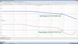
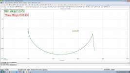
Next thing is Phase and Gain margins. Plot:

According to this explanation of PM and GM, I should have a PM >= 65degree which is good, and that is with CM=30pf. Regarding GM I have to study a little more, that will be in the days to come. I will also do a sim in MicroCap like Mick in post #88.
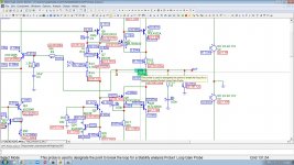
I have been working on the PCB in KiCad:


As usually, I would be happy for comments, suggestions, warnings and what else. The project isn't closed.
Henrik.
Since I am following Cordell's Basic amp design, I have decided to make the triple, emitterfollower + CFP OPS as in the LTSpice schematic here:Bob Cordell in Designing Audio Pwr Amps on page108:
CFP Triples
As with simple Darlington output stages, the conventional two-transistor CFP does not
have adequate current gain to enable the really high performance achievable by lightening
the load on the VAS. As with emitter follower Triples, there are CFP Triples.
Although there are many ways to incorporate three transistors into a CFP, the safest and
most straightforward is to simply precede the CFP with an emitter follower predriver.
It adds two Vbe to the required amount of bias spread and does not change any of the
stability or transconductance characteristics of the CFP.
If I encounter "Thermal Hell" I will pull out Q16 and Q17. If the unconnected tracks will create any problems when pulling out Q16-17, I don't now, time will tell.
Next thing is Phase and Gain margins. Plot:
According to this explanation of PM and GM, I should have a PM >= 65degree which is good, and that is with CM=30pf. Regarding GM I have to study a little more, that will be in the days to come. I will also do a sim in MicroCap like Mick in post #88.
I have been working on the PCB in KiCad:
As usually, I would be happy for comments, suggestions, warnings and what else. The project isn't closed.
Henrik.
- Home
- Amplifiers
- Solid State
- My first CFP power amp