Keep working on it. I planned my speakers in 2011 but never had the time. Look at it now. You never know how things work out. I would grab that UK offer, shipping is easy (lol).
Encase you interested in the nesting.
No smaller circles within the bigger ones? Should be possible to code that on a CNC...
I have already done this, but only on a few as their was a problem if the spaces were beneath 15mm
Taking a closer look at your CAD sketches, it's apparent that we've so far overlooked one obvious point - such a spiral is based on each individual layer's piece being tapered, with as I make it from the second drawing, at least 5 separate angles. This is not something that all CNC routers are capable of, and to provide a glue-ready surface on each would take a huge amount of run time on a 5 axis machine, plus quite possibly wear out some tooling. You can ramp a vertical cut bit to reduce tool stress when plunging, but even with many passes the result would not be smooth enough to provide a flat glue joint area.
With that in mind, the cost of additional material to allow for tool bit correction and efficient cutting paths is rather insignificant.
There's an abbreviation in the woodworking trade; " CCM" - curves cost money, and that's more than squared when you go in all 3 dimensions.
With that in mind, the cost of additional material to allow for tool bit correction and efficient cutting paths is rather insignificant.
There's an abbreviation in the woodworking trade; " CCM" - curves cost money, and that's more than squared when you go in all 3 dimensions.
Last edited:
Which price, UK or French?
The UK price sounds dirt cheap to me, and i'd be wary.
dave
The test samples have been done on a 3 axis machine, though it did take a little while. But the results where great. I'll take some pics tomorrow.
In total, there are 20 different angle. This was to help get a 3m transmission line with a 5" opening.
Chrisb, do you think these are worth making?
In total, there are 20 different angle. This was to help get a 3m transmission line with a 5" opening.
Chrisb, do you think these are worth making?
Also, from my research, these may be the first logarithmic spiral speaker made purely from wood ever made 🙂😀
Maybe so with a round cross-section....
TL Links
dave
Maybe so with a round cross-section....
dave
With a round Cross-section...
do you think these are worth making?
My take is that since these are currently a scuplture and not a design -- you can't do a design without having choosen a driver and designed for it -- it is an intellectual effort only.
dave
The test samples have been done on a 3 axis machine, though it did take a little while. But the results where great. I'll take some pics tomorrow.
In total, there are 20 different angle. This was to help get a 3m transmission line with a 5" opening.
Chrisb, do you think these are worth making?
20 angles? I only measured 5, but you have all the drawings.
No matter what, I could certainly imagine the cost would be significant, if the estimate you gave doesn't get revised once the CNC shop pushes the go button, it's actually quite reasonable - but who am I to say what the result would be "worth"?
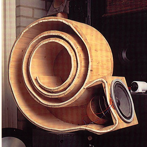
What's interesting about the photo posted by Dave during early development by BW of the Nautilus concept is the apparent use of "rubber" curving plywood. This material is quite flexible and in the sample shown probably exhibited far more wall "constrained layer" and soft material damping properties than layers of multi-ply would. And whether that's good or bad could be argued for days as well 🙄
I also thought you could build them up in layers, with each piece being a figure of eight shape, would be quite hard to get the internal shape perfectly smooth, but is it needed, with steps and random shapes would it break up the standing waves?
Sort of like this idea I had
Sort of like this idea I had
An externally hosted image should be here but it was not working when we last tested it.
That picture looks somewhat familiar 😀...
You mean to slice up the spiral shape in flat sections? You could sand the outer shape perfectly and I wouldn't worry about the less smooth inner shape. It would use up a lot of wood though.
You mean to slice up the spiral shape in flat sections? You could sand the outer shape perfectly and I wouldn't worry about the less smooth inner shape. It would use up a lot of wood though.
Or the sections could be cut out of foam and then sanded smooth and fiber glassed over. I think I mentioned that already. 🙂 the advantage of foam is it is easy to cut and much cheaper than wood. You don't have he mass though - but having a speaker you can pick up with one hand and move from room to room is cool.
That picture looks somewhat familiar 😀...
You mean to slice up the spiral shape in flat sections? You could sand the outer shape perfectly and I wouldn't worry about the less smooth inner shape. It would use up a lot of wood though.
I thought about doing this when I initially started the design. (See Pic) Though the wastage would have been immense.
Also I want to have both a smooth interior and exterior...
Attachments

Or the other option is to glue up lots of mdf as a solid block, and get the CNC to machine out the internal snail shape to form a mould, from which you could take a fibreglass cast.
Would only be one CNC operation, with a lot to remove...
Would only be one CNC operation, with a lot to remove...
I also looked at doing this, but as the project states, this is meant to be an affordable logarithmic spiral speaker. And milling out a solid block of mdf would cost loads. Also, living in the south of france, mdf cost £100 per sheet. (22mm)
Studio au, I am also from bristol... which part?
I will pm you back in a bit. Kids going mad.
Studio au, I am also from bristol... which part?
I will pm you back in a bit. Kids going mad.
If you add labor costs to do it by hand it will never be affordable. The CNC prices will start to look mighty cheap if you start counting hours to do it otherwise.
Be sure to figure out a good way to glue-ing everything together. That is also a very time consuming task with lots of ways to go wrong.
But the most important part (for me) would be finding the right driver to work with the enclosure. Did you figure that out yet? The enclosure has to work with the driver, not against it.
I'd pick a driver first, then work out enclosure dimensions such as total length etc. Would be fun to find something similar to the Manger for such an enclosure.. You have to make certain it's going to work with a job as big as this.
Last edited:
The most affordable way to do this is to prototype it in foam core (or even rolled-up EPS home insulation sheating) first (cost $5 dollars of materials and 3 hours of work) to hear how it sounds before investing any serious time or money on cutting wood. The foam core will give you a very good representation of the sound.
Btw, did I miss it but there has yet to be any mention of a particular driver or T/S parameters? I can easily model the response for this in AkAbak before any physical cutting needs to be made. Need T/S params for driver and approximate dimensions though to do so.
Btw, did I miss it but there has yet to be any mention of a particular driver or T/S parameters? I can easily model the response for this in AkAbak before any physical cutting needs to be made. Need T/S params for driver and approximate dimensions though to do so.
Last edited:
- Status
- Not open for further replies.
- Home
- Loudspeakers
- Full Range
- My first build - Affordable Transmission Line spiralled Loud Speaker