bimo,
can you please take a look on the simulated results of my latest build....clpping is not so good but it is not bad either, I think 🙄
Sa muli,
Albert
can you please take a look on the simulated results of my latest build....clpping is not so good but it is not bad either, I think 🙄
Sa muli,
Albert
Attachments

bimo,
can you please take a look on the simulated results of my latest build....clpping is not so good but it is not bad either, I think 🙄
Sa muli,
Albert
It is OK, because VAS loaded by current mirror. If you want to same clip condition on positive and negative signal, you should use symmetrical VAS.
Hi bimo,
...it means it can be accounted for stability purposes and not some frequency compensation?
No. It just make emitter - collector voltage of VAS transistor did not change, so Early voltage and Cob influence can be minimize.
I tried shunt compensation like Symasym amplifier on your amplifier. But I found it better use ordinary Miller and Miller Input Compensation (MIC - Bob Cordell). If output stage is not CFP it may better use compensation like Symasym did.
It is OK, because VAS loaded by current mirror. If you want to same clip condition on positive and negative signal, you should use symmetrical VAS.
Glad to hear that, I may have to look for symmetrical VAS implementation for other topology. I think the ltp VAS worked out to be just fine in the current circuit, not to mention CFP output topology is a stuborn thing to tame 😛
No. It just make emitter - collector voltage of VAS transistor did not change, so Early voltage and Cob influence can be minimize.
I tried shunt compensation like Symasym amplifier on your amplifier. But I found it better use ordinary Miller and Miller Input Compensation (MIC - Bob Cordell). If output stage is not CFP it may better use compensation like Symasym did.
Calvin had the same impression on the use of standard miller on my circuit, proves to be much stable to work with. By the way I tried to lose the compensation caps on both drivers. Amp worked without oscillation. In my build input ltp current is at 1.2ma but I retained the VAS current at 5ma [Valery's recommendation also].
I have likened the bass response from the adjustment made. When I played Jazz music with it, the bass roll is stunning. very P3A like 😎
Sa muli,
Albert
Your extract does not show what the lead on the cap||LEDs is connected to. How can we help if you omit essential information.Folks,
Anyone care to shed light on the purpose of the LEDs in the attached image? The common base cascode in the balanced VAS is a current error sensor yet this one the base is clamped to minus rail with 3 diodes. This is from one of the late Dr. Bora's VAS design.
Sa Muli,
Albert
What we can tell you is the voltage on the 7uF cap is 3*Vfleds.
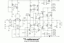
the 3*Vfleds sets the cascode transistor bases to that same voltage.
This in turn sets the second LTP collector voltage to roughly 600mV below 3*Vfleds. Probably ~5V
This in turn sets the second LTP collector voltage to roughly 600mV below 3*Vfleds. Probably ~5V
Note that a reference of 5.1 V set by LEDs is more low-noise than one by a Zener diode.
Best regards!
Best regards!
calvin and bimo,
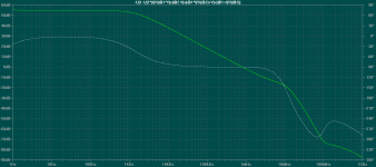
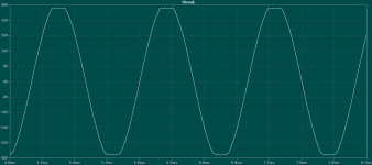
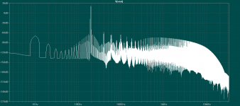
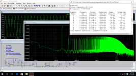
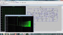
I am tweaking this new cfp design for weeks, THD is very low. Clipping behaviour is symmetrical, loop gain analysis suggests a stable circuit. I am attaching the asc files for you to check, extract all files to a new folder because I am using the measure margins method to plot loop gain. All the needed files should be located in the same folder. Be sure to copy the loop probe asy to the default program sym folder. Let me know if the circuit shows some potential. Attached FFT plot is 20KHz 50w.
Sa muli,
Albert
Attachments
calvin and bimo,
I am tweaking this new cfp design for weeks, THD is very low. Clipping behaviour is symmetrical, loop gain analysis suggests a stable circuit. I am attaching the asc files for you to check, extract all files to a new folder because I am using the measure margins method to plot loop gain. All the needed files should be located in the same folder. Be sure to copy the loop probe asy to the default program sym folder. Let me know if the circuit shows some potential. Attached FFT plot is 20KHz 50w.
Sa muli,
Albert
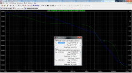
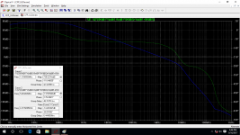
I run your simulation and it give 60 degree phase margin and 7,7dB gain margin. I use Tian probe.
Attachments
The long grass showing in your distortions plot may indicate your settings are not optimised..... loop gain analysis suggests a stable circuit................ Attached FFT plot is 20KHz 50w............
I run your simulation and it give 60 degree phase margin and 7,7dB gain margin. I use Tian probe.
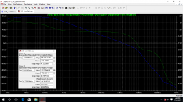
That looks confusing my plot using both XIp and Tian probe are identical.
For Tian I connect the input to ground and set 0 amplitude to voltage sources.
For XIp I connect the supplied input source and also set 0 to voltage sources.
Attachments
The long grass showing in your distortions plot may indicate your settings are not optimised.
Both of my CFP design shows almost the same FFT graph. Harmonics extension goes forever. This is also one of my investigation that needs confirmation. I recall member Sakis having mentioned that CFP Harmonics structure is very different looking.

The LED for voltage reference (similar to zener diode).
yes, and three in series means 3 x 1.7 or a total of 5.1, a bypass cap was used for noise cancellation..used as base reference for the cascodes, a typical trick, some even used plain voltage dividers instead of zeners, Ostripper used those cascodes in the honey badger amp.
The long grass showing in your distortions plot may indicate your settings are not optimised.
i call it funny business, outside of the audio band...
- Status
- Not open for further replies.
- Home
- Amplifiers
- Solid State
- My CFP design, need your help!