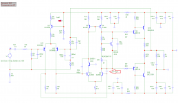
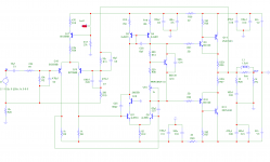
Finally!, It works and was stable, schematic in post #1 is correct. The 100pf across Q11 & Q18
needs to be retained, just like M. Bittner's Symasym design. It only needs adding
a small value capacitor across the paired Q5 (see attached image). With the changes made, the amp was tamed and became silent, feeling confident, I fired it up and played a 14track album, and I must say it works nice and easy. Very good highs and mid, tight and controlled bass too. DC offset was 7mv set it to a low 20ma across both output re (I'm using a small heatsink).
Man, was I so engrossed looking for the right spot to place addt'l compensation that unknowingly the solution was so simple. Great! this is what happens when you download a lot of stuff from the net, some schematic looks so good that when you run it in sim, they give you a confusing results.
I thank you guys for all of your feedback.
Cheers!
Attachments

Thank you, sir! 🙂
I am still working with the values, I found out that the mid frequency is a little aggressive. At minimum volume level the bass is being left behind, but that is with my hearing senses, certainly I'm no audiophile and I'm no disco music lover either. 🙂
I also found out that bias adjustment is very sensitive, I have experimented with trimmer adjust, started adjustment at 0ma then gradually adjust it between intervals of 1ma, 4ma 6ma...and when it reached about 10ma it instantly jumps at 3v. At one time I had it set at 30ma and after playing a few song I re-measured the idle current and surprisingly it was at 3v again! I have read from a few old Symasym threads that some builders are adjusting the value of C25 (100pf).
The amp works at low currents without a problem. I still need to fix bias issues and increase bass response if possible....will appreciate any help.
Regards!
Albert
Member
Joined 2009
Paid Member
A bit of harshness and bias sensitivity might mean some tendency to oscillate, perhaps only near saturation for example. I'd suggest adding a compensation cap across base-collector of the low-side driver, Q10.
For my taste C7 is a bit large (220uF) and C14 a bit small (10uF)
And R37/38 could be smaller, let a bit more current through the drivers.
Bass - not sure, but if you can put large rail decoupling caps near the output stage that is usually a good thing, i.e. C18 and C20 could be 4,700uF each. I assume your speakers are capable of good Bass and the source is not bass shy either so you know it's the amplifier that needs attention ?
Why wouldn't you want the same compensation on Q5 and Q11 ?
Where's the output inductor ?
Last edited:
^Bias issue fixed, it only needs attaching a small value cap (10pf) at the B/C junction of Q4 (same as with an earlier posted schematic).
C14 is THD sensitive , larger value increases THD. R37/38 value is now at 150r. Smaller value here increases heat on drivers and IMD graph looks ugly (at least to me).
I am not so sure on the effect of compensation on Q5 (100pf) I have read that the value can be changed. 47pf comp cap on Q11 is effective, lower value here oscillation is still occuring. I am currently playing with the input bandpass filter, hopefully to allow more low freq. response. My speakers are 6r from a Sharp component (ported type box) and yes they can be boomy if you play a lot of bass music.
Comparing it with my other build like VHex, I could tell that the bass response seemed to be overpowered by the mid frequency. The delicate highs is there but the vocals of the singer seemed to be coming more in front.
Output inductor is present in the pcb, vertical mount like that of the VHex build (Jwilhem's build). I will post my revised schematic later....
Hi,
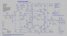
as some parts values occured a bit strange to me, I hacked the circuit into the sim.
Here´s the result ... all modifications are marked with a small ´mod´ label.
parts wo. suffix: LTspice original, or transistors from NXP
w. suffix co --> Cordell models
w. suffix fair --> Fairchild models.
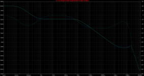
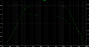
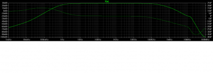
The OL simulation shows a rather low OL-gain over most of the audio band and a possible oscillation issue around 18MHz ... also as visible peak in the amp simu.
The compensation caps C4 and C9 don´t alter anything -at least in simu.
Also C8 seems not necessary at all.
It seems to me that the amp could profit from some more tuning. 😉
jauu
Calvin
as some parts values occured a bit strange to me, I hacked the circuit into the sim.
Here´s the result ... all modifications are marked with a small ´mod´ label.
parts wo. suffix: LTspice original, or transistors from NXP
w. suffix co --> Cordell models
w. suffix fair --> Fairchild models.
The OL simulation shows a rather low OL-gain over most of the audio band and a possible oscillation issue around 18MHz ... also as visible peak in the amp simu.
The compensation caps C4 and C9 don´t alter anything -at least in simu.
Also C8 seems not necessary at all.
It seems to me that the amp could profit from some more tuning. 😉
jauu
Calvin
Attachments
Hi Calvin,
That is very nice of you simulating my schematic in LTSpice. I will definitely look into it in my 2nd channel build. I know you are one of the more knowledgeable members here when it comes to the CFP topology. 😉
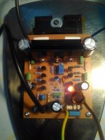
Attached also is the amp and the schematic as presently built, with regards to bass issue I think it was just probably me and my hearing senses, or perhaps I was just blindly comparing it with my other builds and miss the opportunity to define the unique sound of a CFP topology. I do know that to it takes longer hours of burn-in test for an amp to show its true character.
Cheers!
That is very nice of you simulating my schematic in LTSpice. I will definitely look into it in my 2nd channel build. I know you are one of the more knowledgeable members here when it comes to the CFP topology. 😉
Attached also is the amp and the schematic as presently built, with regards to bass issue I think it was just probably me and my hearing senses, or perhaps I was just blindly comparing it with my other builds and miss the opportunity to define the unique sound of a CFP topology. I do know that to it takes longer hours of burn-in test for an amp to show its true character.
Cheers!
Attachments
Calvin,
Do you still have the spice files of this amp? I made new changes in the schematic and tested it in my actual build. It worked nicely, in my sim it doesn't seem to show noticeable changes. Would you mind running the new changes in your LTSpice again?
Thanks!
Regards,
Albert
Do you still have the spice files of this amp? I made new changes in the schematic and tested it in my actual build. It worked nicely, in my sim it doesn't seem to show noticeable changes. Would you mind running the new changes in your LTSpice again?
Thanks!
Regards,
Albert
Attachments
I am posting here the newly revised schematic diagram of this cfp amp. It is my superficial adaptation of Samuel Greoner's push pull VAS improvisation method. It works in my actual build. 🙂
Calvin,
I tried adding RC network parallel at the input diff collectors and also tried another at VAS collectors. THD rises
Calvin,
I tried adding RC network parallel at the input diff collectors and also tried another at VAS collectors. THD rises
Attachments
Congrats!
Your problem solved
My friend have CFP too
But he has no problem from start
But he is so suck cause he didn't give me his schema
Your problem solved
My friend have CFP too
But he has no problem from start
But he is so suck cause he didn't give me his schema
Hi,
only two small compensation caps left ... I like that 😉
When I saw the PCB pic in #27 I wondered though if Your problems might not be due to layout/parts positioning.
The output RL and RC networks look to be close to the input.
I'd expected them close to the power transistors at the other end of the PCB.
If You run the high-current output line across the whole PCB, passing along lowlevel lines, You can expect them to interfere with those lines.
Just recently I did a layout redesign of a phono stage prototype, which resulted in ~20dB improved THD+N figures.
A good layout is important, the more so the touchier the circuit.
Its not uncommon to see tons of compensation caps thrown at circuits to tame what could be cured simply with a new decent layout.
jauu
Calvin
+1......A good layout is important, the more so the touchier the circuit. Its not uncommon to see tons of compensation caps thrown at circuits to tame what could be cured simply with a new decent layout.....

C5 and C6 give a feel of symmetry, but that is far from the truth.
as C6 is coupled across the large voltage gain stage, it has a dominant effect on the input impedance of the transitor fed by the differential pair. C5 is only connected to ground.
run a 100khz sim and look at the symmetry there...
as C6 is coupled across the large voltage gain stage, it has a dominant effect on the input impedance of the transitor fed by the differential pair. C5 is only connected to ground.
run a 100khz sim and look at the symmetry there...
Calvin,
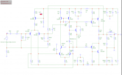
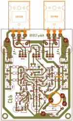
All the new ideas I got is in this paper....and I drop the other comp caps. Voila! it works the circuit became so simple now 😉 The pcb im using was derived from my Symasym (M. Bittner's design) board lay-out, the image below contains old component designation and a few tracks reroute it needs updating . The feedback track looks disconcerting but it did not pose a serious problem in my actual build. The amp is pretty silent, no hiss or any thump. Pretty good sonic details too 😉
Regards,
Albert
Attachments
Congrats!
Your problem solved
My friend have CFP too
But he has no problem from start
But he is so suck cause he didn't give me his schema
fandi,
Hack into his system and stole the files.....
kidding aside 😀
If he doesn't want to share it, get yourself one here in the forum. CFP is a very good sounding amp topology, look for ljm's L12-2 design or Rod's P3A and I think one called Joy amp. Just hit the search button. 🙂
Regards,
Albert
C5 and C6 give a feel of symmetry, but that is far from the truth.
as C6 is coupled across the large voltage gain stage, it has a dominant effect on the input impedance of the transitor fed by the differential pair. C5 is only connected to ground.
run a 100khz sim and look at the symmetry there...
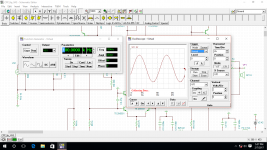
TINA simulation. I was using the slower TIP2955/3055 output device. My sim does not have the model for 2SA1943/5200 device. I've adjusted a few resistor values in VAS to compensate for bias adjustment.
The earlier schematic from previous post (in b/w) is done and simulated in MikroCap, I find MikroCap currents and voltages results more closer in comparison with the actual build plus I have likened its IMD function. 🙂
Attachments

and the comment is?
..sorry bout that Andrew, I was actually showing it to Valery..but since I'm on mobile phone I had to stick it here in the thread.
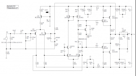
I decided to explore more on this circuit, the new added changes originated from Valerys concept. Valery actually made a whole schematic design out of it.
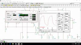
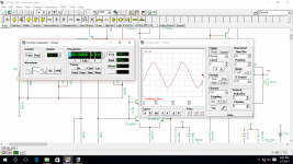
One transistor of VAS current mirror was replaced with 1n4148 for speedier response and with increased current at 4ma, bias stability is much better. Phase lead cap connected to base of +driver improves stability. Hopefully to mitigate HF overshoot.
Input RC network flattens the pointed curve seen at AC analysis approaching 10mhz. [possible oscillation issue?] In my actual build 47pf was increased to 100pf.
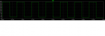
I still had a problem though with squarewave, top swing still shows overshoots. Transient image was at 1khz.
Calvin,
Many thanks for the Spice files I'm still learning a lot here ..😉
Regards,
Albert
Attachments
- Status
- Not open for further replies.
- Home
- Amplifiers
- Solid State
- My CFP design, need your help!