I just fired it up today, everything looks normal no overheating of parts, dc offset is 5mv, it does not seem to be self-oscillating.(no ac volt detected when no signal applied).
Now the problem is, when I connect the meter probes to check on the idle current (output re) , the lamp bulb lights up brightly and the sofstart relay goes off. Same with attaching the speakers, light bulb lights up brightly, I also tried touching the inputs and the lamp bulb lights up again. Powering it on it is normal but when I try to get some measurements, the lamp bulb lights up.
I find this behaviour pretty strange, my first encounter to such amp behaviour, it does not seem to want to be touched..
Attachments
I think your meter and its long leads have added more reactive elements to your prototype and caused the instability you now have. You could try rolling the meter leads together, fitting the shortest possible ones, ferrite beads on the leads, ceramic caps across them etc. but I think there will still be problems if the overall gain is too high.
Check with a 'scope or even a DFM but you'll find it hard to deal with oscillation unless the circuit is laid out with short links between components in the output stage and somewhat lower Ft parts are used.
Check with a 'scope or even a DFM but you'll find it hard to deal with oscillation unless the circuit is laid out with short links between components in the output stage and somewhat lower Ft parts are used.
Those CFP output stage can be really sensitive, I know from repairing a few ( Audiolab 8000A/8200A, Nakamichi PA-5 etc). However when they are stable they sound sooo good.
Try to lower R37+R38 to change the current feedback to the input of the output transistor. Audiolab 8200A uses 47 ohm 1/4W at this spot.
Maybe you could also read through this thread for tips.
Try to lower R37+R38 to change the current feedback to the input of the output transistor. Audiolab 8200A uses 47 ohm 1/4W at this spot.
Maybe you could also read through this thread for tips.
Last edited:
@Ian,
I was also thinking about the overall gain, it could be high enough to cause the amp to be very sensitive...
@Nrik,
Lowering R37/38 increases driver load current, this'll make the drivers more warmer, but I will check that out too...thank you for the link.
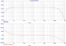
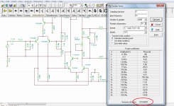
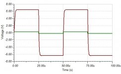
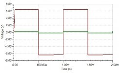
Attached are some simulated results, if you find anything unusual from the topology used, just point it out.
Thanks.
I was also thinking about the overall gain, it could be high enough to cause the amp to be very sensitive...
@Nrik,
Lowering R37/38 increases driver load current, this'll make the drivers more warmer, but I will check that out too...thank you for the link.
Attached are some simulated results, if you find anything unusual from the topology used, just point it out.
Thanks.
Attachments
I think it was S.Groner that showed that the second stage of these SymaSym style amplifiers need the -ve side to have an exact matching capacitor to that on the +ve side. i.e. it needs TWO miller comp caps.
Most of the SymaSym that are posted show only one cap and it is usually shown on the wrong side !
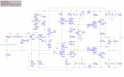
Your 100pf (pF) is shown wrapped around Q11, This is the wrong side. It should be wrapped around Q5 and then duplicated around Q11.
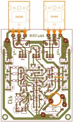
I am going to revisit my 4 different PCB/Layout designs, SymaSym assemblies with this info and try to stop each of them ringing on fast signals. All of them misbehaved and I spent ages trying to get any of them to work properly and abandoned all four.
Most of the SymaSym that are posted show only one cap and it is usually shown on the wrong side !
Your 100pf (pF) is shown wrapped around Q11, This is the wrong side. It should be wrapped around Q5 and then duplicated around Q11.
I am going to revisit my 4 different PCB/Layout designs, SymaSym assemblies with this info and try to stop each of them ringing on fast signals. All of them misbehaved and I spent ages trying to get any of them to work properly and abandoned all four.
Last edited:
Hi Albert,
As Ian and Nrik already mentioned - you get an oscillation because of additional unwanted reactive components, caused by your measurement equipment leads.
CFP is much more prone to oscillation, comparing to Darlington arrangements, because of the local 100% negative feedback.
In some cases, a small value capacitor (47pF or so), between the base of the 1-st transistor in the pair and the rail helps.
Attached is the way Alchemist designer tamed the beast - but that's a rather extreme case - 2 CFP pairs and rather slow output devices. I believe, you will get away with just a single capacitor per each CFP.
Cheers,
Valery
Attachments
I think it was S.Groner that showed that the second stage of these SymaSym style amplifiers need the -ve side to have an exact matching capacitor to that on the +ve side. i.e. it needs TWO miller comp caps.
Most of the SymaSym that are posted show only one cap and it is usually shown on the wrong side !
Your 100pf (pF) is shown wrapped around Q11, This is the wrong side. It should be wrapped around Q5 and then duplicated around Q11.
The second cap being connected to earth.
See details and comments of figure #56 of Groner's http://www.nanovolt.ch/resources/power_amplifiers/pdf/audio_power_amp_design_comments.pdf
Hi guys,
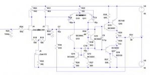
Yes, you can consider the design as a patchwork. It is actually a combination of Bora Jagodic (input stage), Symasym (vas stage) and P3A (output stage). The reason why I omitted some components because I do not see much changes in sim by having them and without them. I have simmed it also in Tina by using the slow TIP devices in the output and it looks pretty good.
@Valery,
That is a lot of compensation....will check that out too...
Yes, you can consider the design as a patchwork. It is actually a combination of Bora Jagodic (input stage), Symasym (vas stage) and P3A (output stage). The reason why I omitted some components because I do not see much changes in sim by having them and without them. I have simmed it also in Tina by using the slow TIP devices in the output and it looks pretty good.
@Valery,
That is a lot of compensation.
...will check that out too...Attachments
well spotted and corrected. Thanks.The second cap being connected to earth.
See details and comments of figure #56 of Groner's http://www.nanovolt.ch/resources/power_amplifiers/pdf/audio_power_amp_design_comments.pdf
fig56 in that paper.
Last edited:
Some encouraging news is: I have never had any stability problems with my CFP prototypes.
I'm for sure not an expert; but look for a ringing using square wave input at the highest frequency still square. (make sure the ringing is not from test equipment)
If you see some attempt at oscillation, simply add a compensation capacitor.
Be careful, many schematics and texts do not show correct location.
BJT CFP are covered fairly well and the gain equations are correct.
Enhancement, depletion, valve and mos CFP hybrids are relatively new frontiers for diy. Old and new patents help but I have not found a textbook that covers it all. Many but not all magazine articles only regurgitate the same old lines.
For more detailed math on BJT types see:
Analog Electronics
Circuits, Systems and Signal Processing
Author(s):
D.I. Crecraft and S. Gergely
ISBN: 978-0-7506-5095-3
a fair use partial attached here but you still need the entire text.
Attachments
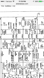
some updates...
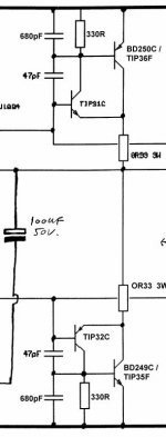
I tried using the location of the compensation caps from the attached image. I also followed Valery's suggestion of attaching a small value cap from base to psu rail of the driver but base to collector seemed to show some improvement but is not enough. The largest value that I used was 56pf on both drivers B/C junction. I also replaced driver load resistor from 220r to 56r (suggested by Nrik). I was hesitant to decrease the over all gain I do think about 29db this should probably not pose a serious problem. Any thoughts on this matter?
I was now able to attach the meter probes without triggering the lamp bulb to full brightness, but still I cannot attach the speakers, and touching the input, the lamp bulb lits up to full brightness again....any more ideas?
Many thanks!
Attachments
this one is cfp preamp but without c3 it will 'ring'.
sometimes just pcb stray capacitance will work.
and the designer was never aware.
http://www.diyaudio.com/forums/solid-state/290026-simple-discrete-sziklai-pre.html#post4714694
i'll try to find a known good schematic with cfp outputs.
sometimes just pcb stray capacitance will work.
and the designer was never aware.
http://www.diyaudio.com/forums/solid-state/290026-simple-discrete-sziklai-pre.html#post4714694
i'll try to find a known good schematic with cfp outputs.
Member
Joined 2009
Paid Member
quick update guys..
I was now able to play some music, but only at low volume, increasing it the lamp bulb lits up....it sounds pretty nice!
I just increased the 10pf to 47pf in the schematic at post #13, no compensation yet at the outputs....will answer to your post later....
Cheers!
I was now able to play some music, but only at low volume, increasing it the lamp bulb lits up....it sounds pretty nice!
I just increased the 10pf to 47pf in the schematic at post #13, no compensation yet at the outputs....will answer to your post later....
Cheers!
- Status
- This old topic is closed. If you want to reopen this topic, contact a moderator using the "Report Post" button.
- Home
- Amplifiers
- Solid State
- My CFP design, need your help!