
I am very late to the party but am in need of 4 boards. Are the Gerber files available, or does anyone have any boards from the previous group buy still available?If there is interest, perhaps we can do a group buy for the boards?
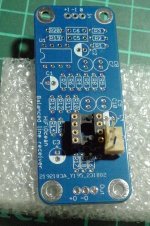
Unfortunately I have no boards left from the group buy. However, I just designed a new board for the same circuit:

After building one and verifying its performance, I have four spare boards of this design. PM me if interested.
The differences from the earlier board are:


The common mode rejection is very much defined by the matching of the resistors. The results shown below are for 0.1% CMF55 resistors (the brown ones in the photo above):


The ground sense reduces the difference between the local ground and that of the downstream device by about 40dB:

The board if relatively wideband:

After building one and verifying its performance, I have four spare boards of this design. PM me if interested.
The differences from the earlier board are:
- Input is now protected by a quad of diodes as suggested above by @Mark Tillotson
- "Normal" size (D=2.5mm L=7mm axial) resistors are used throughout
- More room for input, output and power connectors - Molex KK254 or similar-sized connectors can be used
- Slightly larger board, 50×50mm size (one channel)
The common mode rejection is very much defined by the matching of the resistors. The results shown below are for 0.1% CMF55 resistors (the brown ones in the photo above):
The ground sense reduces the difference between the local ground and that of the downstream device by about 40dB:
The board if relatively wideband:
Oh, it'd be perfect if you built boards that work with Neutrik's PCB-termination XLR jacks. 🙂 Does anyone ever put anything else in between?
https://www.neutrik.com/en/product/nc3fd-h
https://www.neutrik.com/en/product/nc3fd-h
Something like this?

This one is not mine (the source is here, in Russian). This board carries an INA137 and a regulated power supply for it.
I have avoided making PCBs for the public that limit the mechanical layout of the chassis, including connector or knob placement. But as the photo above shows, nothing is impossible.
I was thinking a PCB that would mount by directly soldering to the PCB pins of the Neutrik jack, to save on wiring efforts as well as drilling/tapping/mounting on a sheet or backplate/baseplate. As far as universality goes, Neutrik jacks should be available pretty much anywhere in the world and I don't see any reason they couldn't be shopped for any application.
https://www.audiosciencereview.com/...d-measurements-of-hifiberry-dac-pro-xlr.8569/
https://shop.klotz-ais.com/mis-tx4mk-1.html
These examples above have multiple jacks per board but obviously not a requirement by any means.
https://www.audiosciencereview.com/...d-measurements-of-hifiberry-dac-pro-xlr.8569/
https://shop.klotz-ais.com/mis-tx4mk-1.html
These examples above have multiple jacks per board but obviously not a requirement by any means.
The circuit should work with any unity-gain-stable dual opamps able to drive a 1kOhm load. As mentioned above, the resistor values are optimized for the likes of 4562 and 5532. I tested the board with 5532 (it works well with somewhat lower PSRR vs. 4562) and with TL072 (also work well with higher distortion).
In terms of THD, I got the best results with OPA2156 and/or OPA1656:
Hi Alex,
I'm enclosing measurement results obtained with your PCB in two configurations: 2xLM4562 and OPA1656/OPA2156.
The measurement setup consisted of the Victor's oscillator with a 1656 parallel buffer, Hall topology notch filter (Groner PCB), Groner's 60dB LNA (0.39nV/rtHz) and a Cosmos ADC. The PSU was Jan Diddens's SilentSwitcher, itself supplied by a Power Bank.
The filter represents a load of about 1.8k, so at an output voltage of 2Vrms my measurement results should be comparable to yours at the first page of this thread.
The first measurement, made with 2xLM4562 on the PCB...
https://www.diyaudio.com/community/attachments/balanced-line-receiver-photo-small-png.1166294/
I'd like to use one of these as the 3-pin power header. I note on your build you use a "standard" black linked-square kinda header, which is pretty compact. Do you think there will be enough space between the 3-pin power through-holes and the IC that these would fit?
EDIT: Maybe a right-angle version would be better...
The distance between the holes of the IC and those of the power connector is 150 mil. Your connector needs 125 mil one way and 100 mil, the other, so technically, it will fit. However, two things to keep in mind: (1) if you use an IC socket, that will take away 50 mil from those 150; and (2) the connector's plug may hang out beyond the 100 mil taken by header. The MT-100 IDC plugs look slim on the drawing, but I have no experience with these connectors and can't confirm positively.
The right-angle header should fit, but obviously would need some space outside of the board.
If you want slim polarised headers, something like Molex SL series may be a good fit,
The right-angle header should fit, but obviously would need some space outside of the board.
If you want slim polarised headers, something like Molex SL series may be a good fit,
Like this?Oh, it'd be perfect if you built boards that work with Neutrik's PCB-termination XLR jacks. 🙂 Does anyone ever put anything else in between?
https://www.neutrik.com/en/product/nc3fd-h
https://www.diyaudio.com/community/...-5532-buffer-line-driver.425326/#post-7960405
That's a cute board, but it does not include a difference amplifier. The two halves of the dual opamp buffer and amplify the differential signal, but it remains differential. One would need to add an opamp with four matched resistors, or an INA134 or similar, at the output.
Also, in terms of layout, the area enclosed by each differential pair should be minimized. A mirror-image layout is exactly the wrong way to do it.
Also, in terms of layout, the area enclosed by each differential pair should be minimized. A mirror-image layout is exactly the wrong way to do it.
I just showed the trs/xlr pcb connector. With adapter you can put rca in.
Schematic and board are common used and measure/ sound very good.
No HF/oscillation problems. I use it with opa1612 on adapter, even better.
Drives also 600ohm inputs.
Schematic and board are common used and measure/ sound very good.
No HF/oscillation problems. I use it with opa1612 on adapter, even better.
Drives also 600ohm inputs.
- Home
- Source & Line
- Analog Line Level
- My Balanced Line Receiver